Crystal Considerations with Da
时间:12-28
来源:互联网
点击:
Abstract: This application note describes crystal selection and layout techniques for connecting a 32,768Hz crystal to a real-time clock (RTC). It also provides information about oscillator circuit-design criteria, system design, and manufacturing issues.
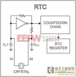
Figure 1. RTC oscillator with internal load capacitors and bias resistors.
In addition to the errors from the crystal and the load match, crystals vary from their base frequency as the ambient temperature changes. Dallas RTCs use "tuning fork" crystals, which exhibit an error over temperature, as shown in Figure 2. An error of 20ppm is equivalent to approximately 1 minute per month.
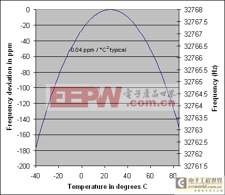
Figure 2. Crystal frequency vs. temperature.
Note: If better accuracy is required, a TCXO such as the DS32kHz can be used.
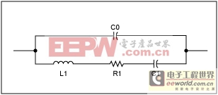
Figure 3. Crystal equivalent circuit.
The load capacitance CL is the capacitive load of the oscillating circuit as seen from the pins of the crystal. Figure 4 shows CL as a capacitance in parallel with the crystal. The load capacitors used in an oscillator circuit, CL1 and CL2, plus any stray capacitance in the circuit, combine to create the overall load capacitance. All Dallas RTCs have integrated CL1 and CL2 capacitors. Care should be taken to minimize stray capacitance in the PC board layout. The following formula shows the relationship between CL and load capacitor values:
CL = [ (CL1 × CL2) / (CL1 + CL2) + CSTRAY]
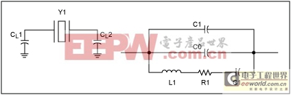
Figure 4. Crystal load capacitors and equivalent parallel load.
Most crystals allow a maximum drive level of 1μW. All Dallas RTCs run under 1μW. Drive level may be determined using the following formula:
P = 2R1 × [π × 32,768(CO + CL)VRMS]2,
where VRMS is the RMS value of the voltage across the crystal.
Table 1. Crystal Specifications
Oscillator Basics
The oscillator used in Dallas Semiconductor RTCs is a CMOS inverter variation of a Pierce-type oscillator. Figure 1 shows a general configuration. These RTCs include integrated load capacitors (CL1 and CL2) and bias resistors. The Pierce oscillator utilizes a crystal operating in parallel-resonance mode. Crystals used in parallel-resonance mode will be specified for a certain frequency with a specific load capacitance. For the oscillator to run at the correct frequency, the oscillator circuit must load the crystal with the correct capacitive load.Figure 1. RTC oscillator with internal load capacitors and bias resistors.
Accuracy
The frequency accuracy of a crystal-based oscillator circuit is mainly dependent upon the accuracy of the crystal and the accuracy of the match between the crystal and the oscillator capacitive load. If the capacitive load is less than the crystal was designed for, the oscillator runs fast. If the capacitive load is greater than what the crystal was designed for, the oscillator runs slow.In addition to the errors from the crystal and the load match, crystals vary from their base frequency as the ambient temperature changes. Dallas RTCs use "tuning fork" crystals, which exhibit an error over temperature, as shown in Figure 2. An error of 20ppm is equivalent to approximately 1 minute per month.
Figure 2. Crystal frequency vs. temperature.
Note: If better accuracy is required, a TCXO such as the DS32kHz can be used.
Crystal Parameters
Figure 3 shows the equivalent circuit for a crystal. Near the resonate frequency the circuit consists of a series circuit including motional inductance L1, motional resistance R1, and motional capacitance C1. The parallel component CO is the shunt capacitance of the crystal.Figure 3. Crystal equivalent circuit.
The load capacitance CL is the capacitive load of the oscillating circuit as seen from the pins of the crystal. Figure 4 shows CL as a capacitance in parallel with the crystal. The load capacitors used in an oscillator circuit, CL1 and CL2, plus any stray capacitance in the circuit, combine to create the overall load capacitance. All Dallas RTCs have integrated CL1 and CL2 capacitors. Care should be taken to minimize stray capacitance in the PC board layout. The following formula shows the relationship between CL and load capacitor values:
CL = [ (CL1 × CL2) / (CL1 + CL2) + CSTRAY]
Figure 4. Crystal load capacitors and equivalent parallel load.
Most crystals allow a maximum drive level of 1μW. All Dallas RTCs run under 1μW. Drive level may be determined using the following formula:
P = 2R1 × [π × 32,768(CO + CL)VRMS]2,
where VRMS is the RMS value of the voltage across the crystal.
Oscillator Startup Time
Oscillator startup times are highly dependent upon crystal characteristics, PC board leakage, and layout. High ESR and excessive capacitive loads are the major contributors to long startup times. A circuit using a crystal with the recommended characteristics and proper layout usually starts within one second.Table 1. Crystal Specifications
| Parameter | Symbol | Min | Typ | Max | Units |
| Nominal Frequency | FO | 32.768 | kHz | ||
| Frequency Tolerance | delta F/ FO | ±20 | ppm | ||
| Load Capacitance | CL | 6 | pF | ||
| Temperature Turnover Point | T0 | 20 | 25 | 30 | °C |
| Parabolic Curvature Constant | k | 0.042 | ppm/°C | ||
| Quality Factor | Q | 40,000 | 70,000 | ||
| Series Resistance | ESR | 45 | kΩ | ||
| Shunt Capacitance | C0 | 1.1 | 1.8 | pF | |
| Capacitance Ratio | C0/C1 | 430 | 600 |
模拟电路 模拟芯片 德州仪器 放大器 ADI 模拟电子 相关文章:
- 12位串行A/D转换器MAX187的应用(10-06)
- AGC中频放大器设计(下)(10-07)
- 低功耗、3V工作电压、精度0.05% 的A/D变换器(10-09)
- PIC16C5X单片机睡眠状态的键唤醒方法(11-16)
- 用简化方法对高可用性系统中的电源进行数字化管理(10-02)
- 利用GM6801实现智能快速充电器设计(11-20)