MAX6652监控系统结合电压监测与温度传感-MAX6652
时间:01-30
来源:互联网
点击:
| Monitored Voltage | MAX6652 Input | Nominal Output Code | -5% Limit | +5% Limit |
| 12 | 12VIN | 192 | 182 | 201 |
| 5 | 3.3VIN (attenuated) | 192 | 182 | 201 |
| 3.3 | VCC (5VIN) | 126 | 120 | 133 |
| 2.5 | 2.5VIN | 192 | 182 | 201 |
Example 3: Low-voltage system.
VCC = 3.3V; monitored voltages are 5V, 3.3V, 2.5V, and 1.8V.The 3.3V supply voltage can be monitored as in Example 2.
The 12VIN pin is available for monitoring the 5V supply. With 5V applied to this input, the output code will be as follows:
192 × 5/12 = 80For alarms 5% above and below the 5V nominal power-supply voltage, we have the following:
high limit = 192 × 5V/12V × 1.05 = 84and
low limit = 192 × 5V/12V × 0.95 = 76The 3.3VIN pin will be used for monitoring the 1.8V supply voltage. With 1.8V applied to this input, the output code (rounded down) will be as follows:
192 × 1.8/3.3 = 104For alarms 5% above and below the 1.8V nominal power-supply voltage, we have (rounded down):
high limit = 192 × 1.8V/3.3V × 1.05 = 109and
low limit = 192 × 1.8V/3.3V × 0.95 = 99The 2.5V input limits are the same as in the first two examples.
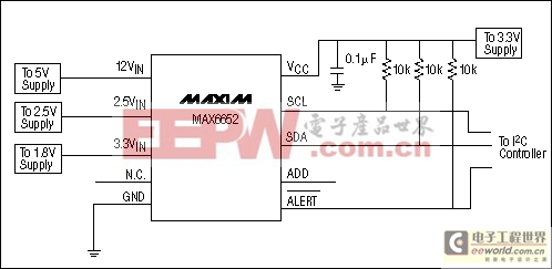
Figure 3. Circuit of Example 3. This circuit is used in a low-voltage system to monitor 5V, 3.3V, 2.5V, and 1.8V. The MAX6652 operates from a 3.3V supply. The 12VIN input monitors the 5V supply, and the 3.3VIN input monitors the 1.8V supply.
Table 3. Output Codes and ±5% Limits for the MAX6652 in a Low-Voltage System, Monitoring 5V, 3.3V, 2.5V, and 1.8V
| Monitored Voltage | MAX6652 Input | Nominal Output Code | -5% Limit | +5% Limit |
| 5 | 12VIN | 80 | 76 | 84 |
| 3.3 | VCC (5VIN) | 126 | 120 | 133 |
| 2.5 | 2.5VIN | 192 | 182 | 201 |
| 1.8 | 3.3VIN | 104 | 99 | 109 |
Example 4: Alternative low-voltage system.
VCC = 3.3V; monitored voltages are 5V, 3.3V, 2.5V, and 1.8V.This is an alternative to Example 3. In this example, the1.8V supply is monitored at the 2.5VIN input instead of at the 3.3VIN input, and the 2.5V supply is monitored at the 3.3VIN input. This improves the measurement resolution for the 1.8V supply, while making the resolution for the 2.5V supply somewhat worse relative to Example 3.
The 3.3V supply voltage is monitored as in Examples 2 and 3.
The 12VIN pin monitors the 5V supply as in Example 3.
The 3.3VIN pin will be used for monitoring the 2.5V supply voltage. With 2.5V applied to this input, the output code (rounded down) will be as follows:
192 × 2.5/3.3 = 145For alarms 5% above and below the 2.5V nominal power-supply voltage, we have (rounded down):
high limit = 192 × 2.5V/3.3V × 1.05 = 152and
low limit = 192 × 2.5V/3.3V × 0.95 = 138
The 2.5VIN pin will be used for monitoring the 1.8V supply voltage. With 1.8V applied to this input, the output code (rounded down) will be as follows:
192 × 1.8/2.5 = 138For alarms 5% above and below the 2.5V nominal power-supply voltage, we have (rounded down):
high limit = 192 × 1.8/2.5 × 1.05 = 145and
low limit = 192 × 1.8/2.5 × 0.95 = 131
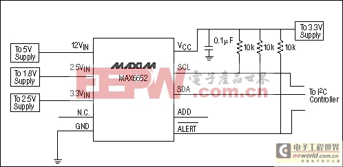
Figure 4. Circuit of Example 4. This circuit is an alternative to the low-voltage circuit in Example 3. Monitored voltages are still 5V, 3.3V, 2.5V, and 1.8V, but the inputs to the 3.3VIN and 2.5VIN pins are swapped to give better resolution when measuring the 1.8V supply.
Table 4. Output Codes and ±5% Limits for the MAX6652 in the Alternative Low-Voltage System, Monitoring 5V, 3.3V, 2.5V, and 1.8V
Note that the 1.8V input voltage produces a larger ADC code, resulting in a higher-resolution measurement.
| Monitored Voltage | MAX6652 Input | Nominal Output Code | -5% Limit | +5% Limit |
| 5 | 12VIN | 80 | 76 | 84 |
| 3.3 | VCC (5VIN) | 126 | 120 | 133 |
| 2.5 | 3.3VIN | 145 | 138 | 152 |
| 1.8 | 2.5VIN | 138 | 131 | 145 |
- 一种通信电源监控系统组网方案的设计(01-05)
- 通信电源监控系统模拟量采集模块的设计(01-05)
- 通信电源监控系统下位机硬件电路的设计(01-05)
- 一种通信用高频开关型整流器监控系统的实现方案(02-13)
- 一种智能电源监控系统的设计(01-16)
- 基于VB的机房计算机电源监控系统(05-01)