MAX6652监控系统结合电压监测与温度传感-MAX6652
This application note shows four examples of how to implement the MAX6652 into a design.
The MAX6652 is a system-monitor chip with a 2-wire digital interface. It automatically monitors system temperature and four voltages, measuring each with an 8-bit analog-to-digital converter (ADC) once every 300ms (max). Temperature and voltage measurements are continuously compared against programmable thresholds: upper and lower thresholds for voltage and a single over-temperature threshold for temperature. When temperature is too high or when a voltage falls outside of the allowed window, an interrupt is generated that notifies the system controller that a problem exists.
The sensitivities of the voltage monitor inputs have been scaled so that inputs of 12V, 5V, 3.3V, and 2.5V will yield ADC output codes of 192 (or 3/4 of full scale). When the voltages being monitored are the same as these nominal values, it is easy to set up alarm thresholds for, say, 5% above and 5% below the nominal voltage levels.
The MAX6652 can also be used to monitor input voltages that are significantly different from the nominal values, provided that the correct detection thresholds are chosen. A few examples will illustrate how this is done.
Example 1: Nominal Case.
VCC = 5V; monitored voltages are 12V, 5V, 3.3V, and 2.5V.In this example, if each voltage is at the nominal value and the ADC has no error, the ADC will produce an output code of 192 for each input. More accurately, the nominal input voltage is the threshold at which the code changes from 191 to 192. Therefore, when we calculate an ideal code, we always round down to the nearest integer value. For alarms 5% above and below the nominal input voltages, we have (rounded down to the nearest integer values):
high limit = 192 × 1.05 = 201and
low limit = 192 × 0.95 = 182The total unadjusted error of the ADC is 1% of full scale (maximum) or 2.56LSBs, so consider this potential error when choosing voltage limits.
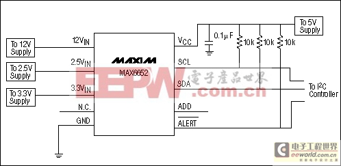
Figure 1. Circuit of Example 1. All input voltages are at the nominal values.
Table 1. Output Codes and ±5% Limits for the MAX6652 Used to Monitor the Nominal Power-Supply Voltages
| Monitored Voltage | MAX6652 Input | Nominal Output Code | -5% Limit | +5% Limit |
| 12 | 12VIN | 192 | 182 | 201 |
| 5 | VCC (5VIN) | 192 | 182 | 201 |
| 3.3 | 3.3VIN | 192 | 182 | 201 |
| 2.5 | 2.5VIN | 192 | 182 | 201 |
Example 2: VCC = 3.3V.
Monitored voltages are 12V, 5V, 3.3V, and 2.5V.This example is similar to the first one, except that the MAX6652 operates from a 3.3V supply instead of the nominal 5V supply. Measuring the 3.3V supply is simple. First calculate the code that corresponds to 3.3V at the VCC pin (rounded down to the nearest integer value):
192 × 3.3V/5V = 126Then calculate the codes for the high and low limits, again rounded down to the nearest integer values. For alarms 5% above and below the 3.3V nominal power-supply voltage, we have the following:
high limit = 192 × 3.3V/5V × 1.05 = 133and
low limit = 192 × 3.3V/5V × 0.95 = 120
Monitoring 5V is more difficult in this example. The 5V can't be applied directly to the 3.3VIN input, because that input is scaled for a maximum input voltage of 4.383V. A resistive voltage divider, as shown in Figure 2, attenuates the 5V supply so that it can be measured at the 3.3VIN input. Using a 39kΩ and a 20kΩ resistor, 5V applied to the divider results in a voltage at the 3.3VIN pin of:
VIN = 5V × 39kΩ/59kΩ = 3.305V
This produces a code equal to 192, so the ±5% thresholds are at 182 and 201.
The limits for the 12V and 2.5V inputs are the same as in the first example.
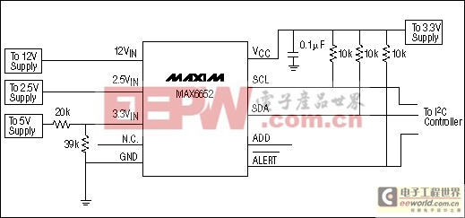
Figure 2. Circuit of Example 2. The same as Example 1, but the MAX6652 operates from a 3.3V supply, which necessitates attenuating the 5V supply so that it can be monitored at the 3.3VIN input.
Table 2. Output Codes and ±5% Limits for the MAX6652, Monitoring the Nominal Power-Supply Voltages but with a 3.3V Supply Voltage for the MAX6652
- 一种通信电源监控系统组网方案的设计(01-05)
- 通信电源监控系统模拟量采集模块的设计(01-05)
- 通信电源监控系统下位机硬件电路的设计(01-05)
- 一种通信用高频开关型整流器监控系统的实现方案(02-13)
- 一种智能电源监控系统的设计(01-16)
- 基于VB的机房计算机电源监控系统(05-01)