ESD保护I/O端口
时间:03-24
来源:本站整理
点击:
Both offer ratings according to the lowest-voltage failure on any pin-an approach that may not do justice to the higher levels of internal ESD protection required by the I/O pins (and provided by some manufacturers). A device might have I/O pins that withstand ±15kV, for example, and non-I/O pins that fail at ±2kV. With the above methods, the device's ESD rating would be less than ±2kV. Fortunately, however, better test methods are now available for rating the I/O pins.
New ESD Tests for I/O Ports
An I/O port allows communication with other pieces of equipment. I/O ports for ICs comprise logical groups of pins that give access to equipment external to the system that contains the IC. These pins are subject to static discharge and other abuse as operators connect and disconnect cables from the system. For the I/O pins of an RS-232 or RS-485 interface IC, an ideal test method for ESD susceptibility should:- Test the I/O pins only in ways that simulate exposure to ESD events in actual equipment.
- Apply test waveforms that model electrostatic discharges produced by the human body. Different circuit models specify different values of amplitude, rise/fall time, and transferred power.
- Test the IC with and without power applied.
- Define IC failures to include latchup (a momentary loss of operation), as well as catastrophic or parametric failure. Latchup is considered a failure mechanism because if left undetected, it can lead to reliability problems and system malfunctions.
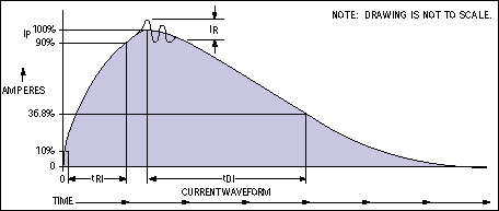
Figure 3. This ESD waveform's parameters (rise time, peak current, ringing, and decay time) are specified in MIL-STD-883 method 3015.7.
Like the original Method 3015.7, the modified method defines only an ESD waveform and the criteria for failure: after exposure to the waveform, a failed IC must either exhibit latchup or fail one or more data sheet specifications. The modified method stipulates no particular operating mode for the IC during test, but Maxim recommends that all possible modes be exercised: power on/off, transmitter outputs high/low, standby/normal operation, etc.
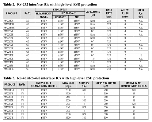
Similarly, the modified method 3015.7 does not compel products to withstand particular levels of ESD; it only defines classes of protection. New transceivers from Maxim, however, generally provide protection levels to ±15kV (Tables 2 and 3). This level allows some users to eliminate costly TransZorbs™; and other external protection circuitry.
IEC 1000-4-2 Model
The second, more stringent method for testing ICs that include I/O pins is IEC 1000-4-2. This equipment-level test was developed by the International Electrotechnical Commission. Originally intended as an acceptance condition for equipment to be sold in Europe, it is rapidly gaining acceptance as a standard ESD criterion in the United States and Japan as well. Though not originally intended as an IC specification, it now does extra duty as an ESD test for ICs. Like the modification to 3015.7, it tests only the I/O pins.The model for IEC 1000-4-2 is again the circuit of Figure 2, but with different component values. The resistance R2 (330Ω) represents a human holding a screwdriver or other metallic object, and C1 (150pF) represents another estimate of human-body capacitance. This circuit produces a current waveform (Figure 4) with a rise time steeper than that produced by Method 3015.7.
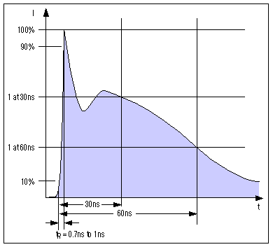
Figure 4. Parameters for this ESD waveform (rise time, peak current, amplitude at 30ns, and amplitude at 60ns) are specified by IEC 1000-4-2.
IEC 1000-4-2 specifies ESD testing both by contact discharge and by air discharge. ESD events caused by actual contact are more repeatable but less realistic, and air discharge is more realistic but subject to wide differences in waveform shape—according to variations in temperature, humidity, barometric pressure, distance between IC and electrode, and rate of approach to the IC pin. (This change of shape can have a significant effect on the measured level of tolerance for ESD.)
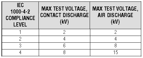
IEC 1000-4-2 defines four levels of compliance (Table 4) according to the lowest maximum voltage withstood by the I/O pins. The table defines these levels both for contact discharge and for air discharge.
Table 4. IEC 1000-4-2 Compliance Levels
Contact or Air Discharge?
Testing ICs for ESD ruggedness per IEC 1000-4-2 requires the use of an ESD "gun," which allows testing with either contact discharge or air discharge. Contact discharge requires physical contact between the gun and the I/O pin before test voltage is applied by a switch internal to the gun. Air discharge requires the gun to be charged with test voltage before it approaches the I/O pin (from the perpendicular, and as quickly as possible). The second technique produces a spark at some critical distance from the test unit.ESD produced by air discharge resembles actual ESD events. But, like actual ESD, the air-discharge variety is not readily duplicated. It depends on many variables that are not easily controlled. Thus, attesting to the general importance of repeatability in testing, IEC 1000-4-2 recommends contact discharge, and the modified 3015.7 method requires contact discharge only. In either case, the test procedure calls for at least 10 discharges at each test level.
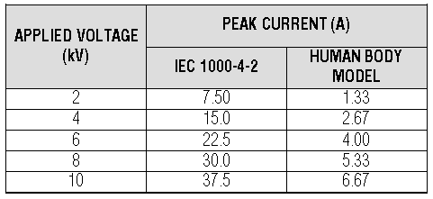
The main difference between the two ESD standards just discussed—the modified 3015.7 method and the air- or contact-discharge version of IEC 1000-4-2—is in the peak currents they produce in the device under test. Different component values can cause these peak currents to differ by a factor greater than five (Table 5). Because peak currents produce the unwanted power that an IC must dissipate, IEC 1000-4-2 is usually the more demanding test method for ESD.
Table 5. ESD Current vs. Model and Applied Voltage
High current can damage an IC in various ways:
- LinkSwitch的电磁兼容性设计(07-10)
- EMI防治技巧与挑战(03-19)
- 用最佳终端匹配策略降低电磁辐射的干扰(02-11)
- 电磁干扰(EMI)抑制技术(03-10)
- 汽车元件的EMI抗扰性测试(04-02)
- 通过PCB分层堆叠设计控制EMI辐射(04-02)
