MAX44009环境光传感器LCD背光亮度的控制应用
最后一步就是在传感器和执行器之间建立连接,通过微控制器实现。有人可能首先要问:"环境光强如何映射到背光亮度?"事实上,有些文献专门介绍了相关方案。其中一种映射方式是,Microsoft®针对运行Windows® 7¹操作系统的计算机提出的。图7所示曲线是由Microsoft提供的,它可以将环境光强度映射到显示屏亮度(以全部亮度的百分比表示)。
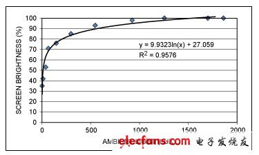
图7. 将环境光强映射为最佳显示屏亮度的曲线示例
这种特殊曲线可以用以下函数表示:
如果设备采用的是已集成亮度控制功能的LCD控制芯片,就可通过向芯片发送指令,轻松设置背光亮度。如果设备采用的是PWM直接控制亮度,则要考虑如何将比例信号映射至显示屏亮度。
在MAX1698示例中,根据其产品说明书的介绍,可以将驱动电流映射为电压。通过这个示例,我们可以假设LED电流强度几乎与其电流呈线性关系。这样,我们就可以在上述等式中乘上一个系数,计算出PWM所映射的有效电压,该电压再被映射至LED电流,最后转化成显示屏亮度。
方案实施
最好不要从一个亮度级直接跳转到另一个亮度级,而是平滑上调和下调背光亮度,确保不同亮度等级之间无缝过渡。为了达到这一目的,最好采用带有固定或不同亮度步长、可逐步调节亮度的定时中断,也可采用带有可控制LED输入电流的PWM值的定时中断,或者是能够发送到显示屏控制器的串行指令的定时中断。图8提供了这种算法的一个示例。
图8. 步进式亮度调节的算法示例
另一个问题是,系统响应环境光强变化的速度。我们应尽量避免过快地改变亮度等级。这是因为光强的瞬间变化(譬如一扇窗户打开或瞬间有一束光扫过)可能导致背光亮度发生不必要的变化,这往往会造成用户感觉不适。并且,较长的响应时间还有助于减少微控制器对光传感器的检测次数,从而可以释放一定的微控制器资源。
最初级的方法就是每隔一两秒钟检查一次光传感器,然后相应地调整背光亮度。更好的方法是,只有光线强度偏离特定范围一定时间后,才对背光亮度进行调节。譬如,如果正常光强是200lux,我们可能只会在光强降到180lux以下或升至220lux以上,而且持续时间超过数秒的情况下才调节亮度。幸运的是,MAX9635和MAX44009都集成了中断引脚和阈值寄存器,可轻松实现这个目的。请参考应用笔记4786"MAX9635环境光传感器的接口程序",获取更多详细信息。
源代码
#define MAX44009_ADDR	0x96
// begin definiTIon of slave addresses for MAX44009
#define INT_STATUS	0x00
#define INT_ENABLE	0x01
#define CONFIG_REG	0x02
#define HIGH_BYTE	0x03
#define LOW_BYTE	0x04
#define THRESH_HIGH	0x05
#define THRESH_LOW	0x06
#define THRESH_TIMER	0x07
// end definiTIon of slave addresses for MAX44009

extern float SCALE_FACTOR;	// captures scaling factors to map from % brightness to PWM
float currentBright_pct;	// the current screen brightness, in % of maximum
float desiredBright_pct;	// the desired screen brightness, in % of maximum
float stepSize;			// the step size to use to go from the current
				// brightness to the desired brightness
uint8 lightReadingCounter;

/**
 *	FuncTIon:	SetPWMDutyCycle
 *
 *	Arguments:	uint16 dc - desired duty cycle
 *
 *	Returns:	none
 *
 *	Description:	Sets the duty cycle of a 16-bit PWM, assuming that in this
 *			architecture, 0x0000 = 0% duty cycle
 * 			0x7FFF = 50% and 0xFFFF = 100%
**/
extern void SetPWMDutyCycle(uint16 dc);

/**
 *	Function:	I2C_WriteByte
 *
 *	Arguments:	uint8 slaveAddr - address of the slave device
 *			uint8 command - destination register in slave device
 *			uint8 data - data to write to the register
 *
 *	Returns:	ACK bit
 *
 *	Description:	Performs necessary functions to send one byte of data to a
 *			specified register in a specific device on the I2C bus
**/
uint8 2C_WriteByte(uint8 slaveAddr, uint8 command, uint8 data);

/**
 *	Function:	I2C_ReadByte
 *
 * 	Arguments:	uint8 slaveAddr - address of the slave device
 *			uint8 command - destination register in slave device
 *			uint8 *data - pointer data to read from the register
 *
 *	Returns:	ACK bit
 *
 *	Description:	Performs necessary functions to get one byte of data from a
 *			specified register in a specific device	on the I2C bus
**/
uint8 I2C_ReadByte(uint8 slaveAddr, uint8 command, uint8* data);

/**
 *	Function:	getPctBrightFromLuxReading
 *
 *	Arguments:	float lux - the pre-computed ambient light level
 *
 *	Returns:	The % of maximum brightness to which the backlight should be set
 *			given the ambient light (0 to 1.0)
 *
 *	Description:	Uses a function to map the ambient light level to a backlight
 *			brightness by using a predetermined function
**/
float getPctBrightFromLuxReading(float lux);

/**
 *	Function:	mapPctBrighttoPWM
 *
 *	Arguments:	float pct
 *
 *	Returns:	PWM counts needed to achieve the specified % brightness (as
 *			determined by some scaling factors)
**/
uint16 mapPctBrighttoPWM(float pct);

/**
 *	Function:	getLightLevel
 *
 *	Arguments:	n/a
 *
 *	Returns:	the ambient light level, in lux
 *
 *	Description:	Reads both the light registers on the device and returns the
 *			computed light level
**/
float getLightLevel(void);

/**
 *	Function:	stepBrightness
 *
 *	Arguments:	n/a
 *
 *	Returns:	n/a
 *
 *	Description:	This function would be called by an interrupt. It looks at the
 *			current brightness setting, then the desired brightness setting.
 *			If there is a difference between the two, the current brightness
 *			setting is stepped closer to its goal.
**/
void stepBrightness(void);

/**
 *	Function:	timerISR
 *
 *	Arguments:	n/a
 *
 *	Returns:	n/a
 *
 *	Description:	An interrupt service routine which fires every 100ms or so. This
 *			handles all the ambient light sensor and backlight
 *			control code.
**/
void timerISR(void);

void main() {

	SetupMicro();				// some subroutine which initializes this CPU

	I2C_WriteByte(MAX44009_ADDR, CONFIG_REG, 0x80);	// set to run continuously

	lightReadingCounter = 0;
	stepSize = .01;
	currentBright_pct = 0.5;
	desiredBright_pct = 0.5;
	SetPWMDutyCycle(mapPctBrighttoPWM(currentBright_pct));
	InitializeTimerInterrupt();		// set this to fire every 100ms

	while(1) {
		// do whatever else you need here, the LCD control is done in interrupts
		Idle();
	}
} // main routine

// the point at which the function clips to 100%
#define MAXIMUM_LUX_BREAKPOINT	1254.0
float getPctBrightFromLuxReading(float lux) {
	if (lux > MAXIMUM_LUX_BREAKPOINT)
		return 1.0;
	else
		return (9.9323*log(x) + 27.059)/100.0;
} // getPctBrightFromLuxReading

uint16 mapPctBrighttoPWM(float pct) {
	return (uint16)(0xFFFF * pct * SCALE_FACTOR);
} // mapPctBrighttoPWM

float getLightLevel(void) {
	uint8* lowByte;
	uint8* highByte;
	uint8 exponent;
	uint8 mantissa;
	float result;

	I2C_ReadByte(MAX44009_ADDR, HIGH_BYTE, highByte);
	I2C_ReadByte(MAX44009_ADDR, LOW_BYTE, lowByte);

	exponent = (highByte & 0xF0) >> 4;// upper four bits of high byte register
	mantissa = (highByte & 0x0F) << 4;// lower four bits of high byte register =
 					  // upper four bits of mantissa
	mantissa += lowByte & 0x0F; 	  // lower four bits of low byte register =
					  // lower four bits of mantissa

	result = mantissa * (1 << exponent) * 0.045;

	return result;
} //getLightLevel

void stepBrightness(void) {
	// if current is at desired, don't do anything
	if (currentBright_pct == desiredBright_pct)
		return;
	// is the current brightness above the desired brightness?
	else if (currentBright_pct > desiredBright_pct) {
		// is the difference between the two less than one step?
		if ( (currentBright_pct-stepSize) < desiredBright_pct)
			currentBright_pct = desiredBright_pct;
		else
			currentBright_pct -= stepSize;
	} // else if
	else if (currentBright_pct < desiredBright_pct) {
		// is the difference between the two less than one step?
		if ( (currentBright_pct+stepSize) > desiredBright_pct)
			currentBright_pct = desiredBright_pct;
		else
			currentBright_pct += stepSize;
	} // else if

	SetPWMDutyCycle(mapPctBrighttoPWM(currentBright_pct));
	return;
} // stepBrightness

void timerISR(void) {
	float lux;
	float pctDiff;

	stepBrightness();
	if (lightReadingCounter)
		lightReadingCounter--;
	else {
		lightReadingCounter = 20;	// 2 second delay
		lux = getLightLevel();
		desiredBright_pct = getPctBrightFromLuxReading(lux);
		pctDiff = abs(desiredBright_pct - currentBright_pct);
		stepSize = (pctDiff <= 0.01) ? 0.01:pctDiff/10;
	} // else

	ClearInterruptFlag();
} // timerISR
- 能源有限!智能电网基础解读(09-14)
- MAX9635内置ADC的环境光传感器(02-11)
- MAX44007环境光传感器,改善黑色玻璃的设计性能(03-21)
- 接近传感器为你揭秘:智能手机是否真的智能(06-02)
- 新型高清显示技术优劣对比(11-13)
- 品佳集团推出LCD TV一系列应用解决方案(08-11)