Rhythm R3710预配置DSP系统实践应用指南
VC pin indicates a gain increase while closure to the D_VC pin indicates a gain decrease. Figure 7 shows how to wire the digital volume control to Rhythm R3710. The digital volume control can be setup to adjust both volume levels and memory configurations depending on the length of time the momentary switch is depressed. It is also possible to read and write the digital volume control with the ARK software. Using these software functions will lock out the digital volume control until the next time the hybrid is powered on. Figure 7. Wiring for Digital Volume Control Memory Select Switches One or two, two−pole Memory Select (MS) switches can be used with Rhythm R3710. This enables users tremendous flexibility in switching between configurations. These switches may be either momentary or static and are configurable to be either pull−up or pull−down through the settings tab in IDS. Up to four memories can be configured on Rhythm R3710. Memory A must always be valid. All memory select options are selectable via the settings tab in IDS. Momentary Switch on MS1 This mode uses a single momentary switch on MS1 (Pin 10) to change memories. Using this mode causes the part to start in memory A, and whenever the button is pressed, the next valid memory is loaded. When the user is in the last valid memory, a button press causes memory A to be loaded. This mode is set by programming the ‘MSSMode’ parameter to ‘Momentary’ and ‘Donly’ to ‘disabled’. Example: If 4 valid memories: ABCDABCDA If 3 valid memories: ABCABCA If 2 valid memories: ABABA If 1 valid memory: AAA Momentary Switch on MS1, Static Switch on MS2 (Jump to Last Memory) This mode uses a static switch on MS2 (Pin 9) and a momentary switch on MS1 (Pin 10) to change memories. If the static switch is OPEN, the part starts in memory A and the momentary switch is enabled, with the exception that memory D is not used. If the pull−up/pull−down resistors are set to pull−down, and the static switch on MS2 is set to HIGH, the part automatically jumps to memory D (occurs on startup or during normal operation). If the pull−up/pull−down resistors are set to pull−up, and the static switch on MS2 is set to LOW, the part automatically jumps to memory D (occurs on startup or during normal operation). In the above setup when the static switch is CLOSED, the momentary switch is disabled, preventing memory select beeps from occurring. When MS2 is set to OPEN, the part returns to the last select memory. This mode is set by programming the ‘MSSMode’ parameter to ‘Momentary’ and ‘Donly’ to ‘enabled’. Example: When MS2 = OPEN, then MS1 can cycle through up to 3 valid memories: ABCABCA… If Pull−up/Pull−down = Pull−down and MS2 = HIGH: D, then memory D is enabled If Pull−up/Pull−down = Pull−up and MS2 = LOW: D, then memory D is enabled Table 5. DYNAMIC EXAMPLE WITH FOUR VALID MEMORIES AND MS2 PULL−UP/PULL−DOWN = PULL−DOWN (T = MOMENTARY SWITCH IS TOGGLED; 0 = OPEN; 1 = HIGH) Static Switch on MS1 and MS2 This mode uses two static switches to change memories. Table 6 describes which memory is selected depending on the state of the switches. In this mode, it is possible to jump from any memory to any other memory simply by changing the state of both switches. If both switches are changed simultaneously, then the transition is smooth. Otherwise, if one swi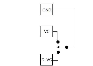
- Rhythm R3710预配置DSP混合系统重点详析(07-14)
- Rhythm R3710预配置DSP系统设计所需规范详析(07-14)