is it possible to measure a negative resistance
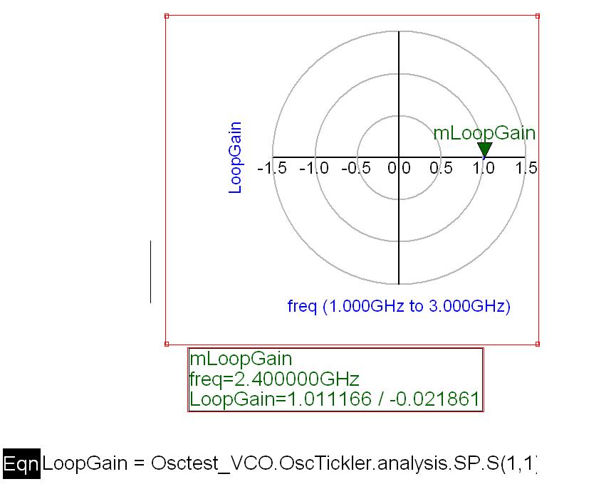
I simulate for oscillation condition for my common base topology VCO in ADS with osctest. I don't know what the zo in osctest means. normally zo in osctest should be 1.1ohms. why? actually osctest is to get the S11, but why should say S11 from osctest is loopgain? Why S11 so called loop gain in nyquist plot should have magnitude larger than 1 and phase around 0 so as to have the potential to oscillate?
How can I get the negative resistance value from this ADS simulation?
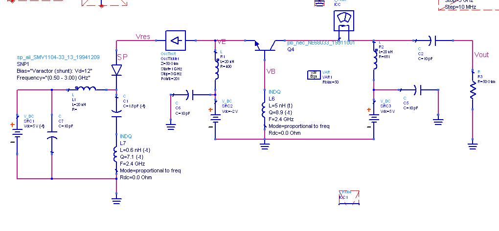
My VCO schematic:
My simulation results:
u can get input impedance by sparameter(1port) or ac simulation(a current source is required).
Negative resistance is calculated from real(Z(1,1))..
I think osctest only shows relative tendency.
Looking at Y-parameters is easier.
simply remove the resonator and replace it with S paramter port , and measure the impedance don't forget to use coupling cap so the 5o ohm port doesn't affect the bias point of the CB
khouly
Follow what Khouly has said then
Also There is a Impedance measuring option in ADS on left side menu in S parameter list.
Place "Zin" Tool in schematic.
Then simulate.
When the output window opens.
add rectangular graph-> select zin->select real part
and say ok
you will see the graph freq vs impedance
measure resistance 相关文章:
- How do I know if a spectrum analyzer is enough to measure an specficic DAC?
- Using ADS2019, How to set and measure tempature values for LNA?
- H field measurements with waveguide twist
- How can I measure the Side-Band Amplitude?
- Keysight PNA Harmonics measurements
- frequency shift between simulation and measurements