site:www.edaboard.com multisection
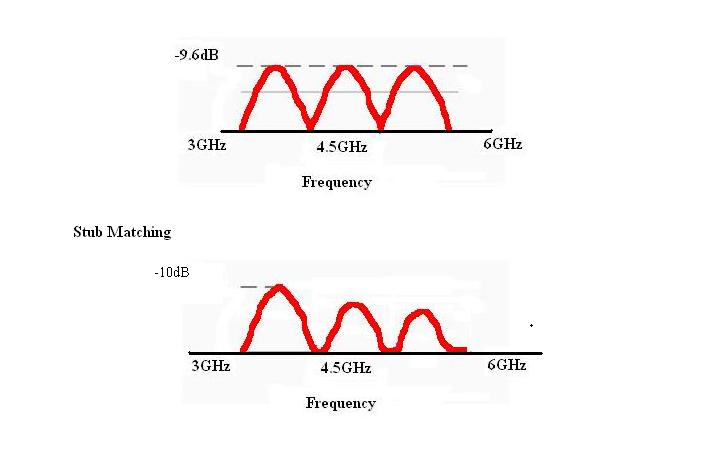
i was designed 15dB cavity type coupler (700Mhz-6000MHz) and simulated in HFSS. after fabricated and 3 spikes were observed at 3.69GHz, 4.5GHz, and 5.7GHz.
spikes were removed by reducing the 50 Ohm line lengths, but not able to reduce the return loss.........
coupler is made by coupler parallel lines (asymmetric lines). Multiple sections are cascaded to increase the bandwidth. (thickness of the conductor = 3mm, Ground plane spacing = 7mm, air as the dielectric media)
How can i impove the return loss?
thanking in advance
Please share the design or rough layout to understand more also test results if any.
hi,
with the addition of stubs, the return loss was improved to -15dB all over the band except at 4500MHz, where it is around -10dB. Frequency of operation 700MHz-6000MHz.
i am trying to optimize stubs to get better return loss all over the band
if any other method to improve it pl. let me know
thank you
chandregowda
Stubs are frequency sensitive I do not know how you got wide band coupler.
hi,
stubs are frequency sensitive, we are trying with different configs
From the picture its cascaded 3 stage couplers.
RL improvement is by the matching of even and odd mode impedance of these individual couplers.
You can observer the same by placing the tuner stubs near the junction.
hi,
it is of cascaded or multisection coupler. started with 3 sections, now it is of 5 sections.
also i am finding its very difficult to match with tuning stubs, as the return loss will improve in one band and it may go bad in one or more bands in the frequency band of operation.
i calculated the width(w) and separtion(s) between the strips from EVEN and ODD impedance of each section (referred to paper: Tables for assymetric multi-element coupled transmission line directional coupler by Ralph Levy).
using ADS calculators, we calculated the width and separation(w, s)
how do we match Zeven and Zodd of each section to improve the return loss?
is it that i have to simulate/optimized each individual section separately for better return loss and then cascade?
thank you
Individual sections are well defined and hence I do not suspect their behavior how ever in a cascaded network you need to simulate and optimize the network. ADS Momentum is the best tool to help you.
The discontinuities between the multi section coupler are not accounted in tabular equations hence getting poor RL. Do the EM simulation and you need to do the tapering for these inter stage connections.
hi,
the parallel lines were of considerable thickness (T=3mm), hence 3D simulations. measured results were well matched with HFSS simulations.