Ferrite balun
thanks
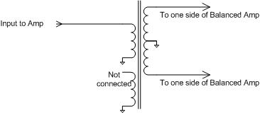
I'm not quite sure but I think that two twisted pairs would be winded on the core. You use twisted pairs to get a transmission line transformer for higher frequency operation. This is equivalent to reducing the parasitic capacitance. I assume the unconnected winding is one of both threads of the primary that is not used because a 4:1 impedance transformation is needed.
tnx Radiohead,
Know of any write-up on this? I've been looking through the books and found nothing.
This approach of using an extra coupled inductor for reducing the parasitic capacitance is used not only on ferrite baluns, but also when designing planar printed baluns. In this way the SRF of the balun can be increased more than 30%.
Tnx Vfone & Radiohead,
I can see how the capacitance to ground between the windings will increase. What capacitance decreases and how? I've started combing thru IEEE papers and still don't get it.