Modulator for RFID
My circuit is based on: www.mwrf.com/Files/30/13722/Figure_04.gif
Thank You.
Do you see any reason, why the circuit should operate as a modulator? I assume a drawing error.
Your schematic should works under condition that the MOS M1 acts as a varactor. You can find details at the following link:
http://www.iannaccone.org/data/95.pdf
regards.
In the circuit as shown, M2 is shorting the output.
Why M2 is shorting the output? According to the journal, M2 works as a resistor so that negligible power at antenna goes to modulator.
I feed a carrier (900MHz) at Cout and i measure my output at the same point using bi-port. Is the way i measure wrong or correct?
Thanks.
I think you should use a model of your antenna (probably an RLC), connected in parallel to Cout, receiving the carrier frequency (900 MHz). Then you should measure the scattered signal by means of a directional coupler.
The RLC circuit for antenna model is series RLC or parallel RLC?
I am using Mentor Graphics for my simulation. Can I know how to construct the directional coupler in Mentor Graphics?
It depends from the antenna type you are going to use: an open dipole can be seen as a series RLC, a loop antenna, insetead, by means of a parallel RLC. These models are a first oredr approximation of the actual model and are valid close to the resonance. I never used mentor Graphic simulator, so I don't know how to model a directional coupler. I'm thinkink, if you can use an alternative method.
Is it the output waveform correct?
I measured the waveform between the antenna model and the modulator.
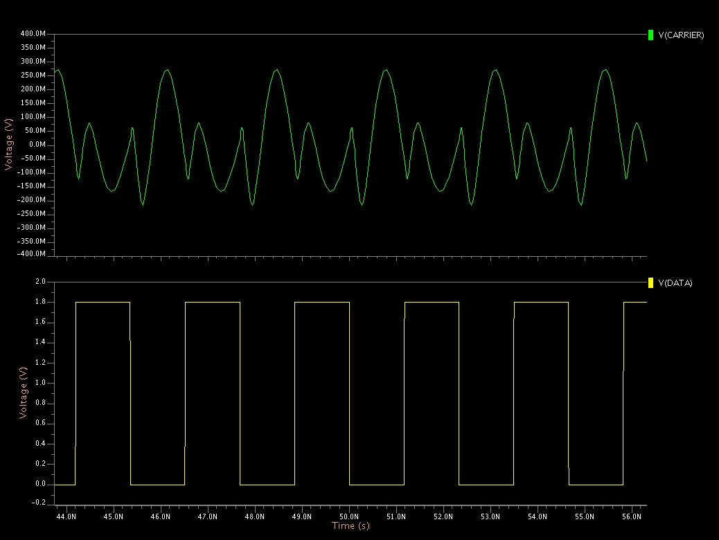
The waveform is in principle quite correct, beacuse you have a phase reversal at each transition, but it seems that there is some amplitude issue. Just a couple of things:
1) the data-rate, in your simulation, is very high: the same as the carrier frequency. I think you should reduce it to have a better idea about amplitude distortion when the transition occours.
2) If you send to the modulator pseudo-random datas, instead of a clock, you should be able to see also the eye-diagram using accumulated plots.
Regards.
I used a lower data rate for my simulation. I found out that the amplitude is overshoot at the transitions.
How to overcome the amplitude problem?
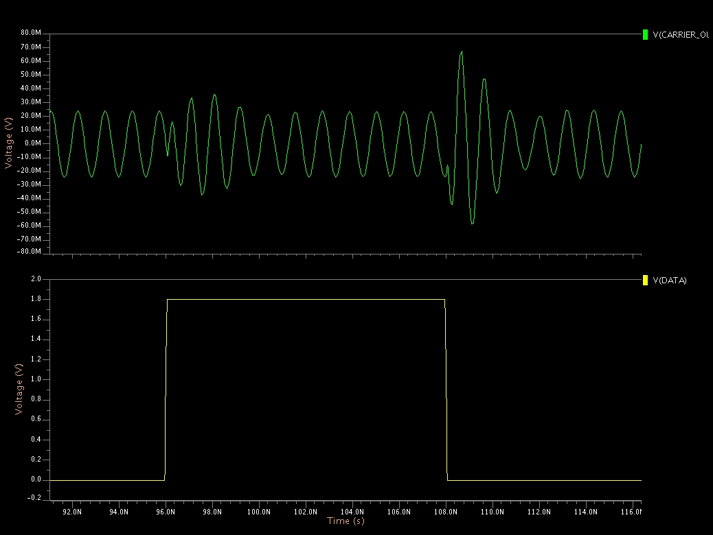
The edges of you data signal are very sharp. I think a transmission filter should be used on data before they are sent to the modulator. You can just try to slow the rise/fall time of the data generator in your simulation. You can also try to reduce the Q of the system putting a low-value resistor in series to the antenna.
Regards.