1.5 GHz Bandpass Filter Help
Thank you.

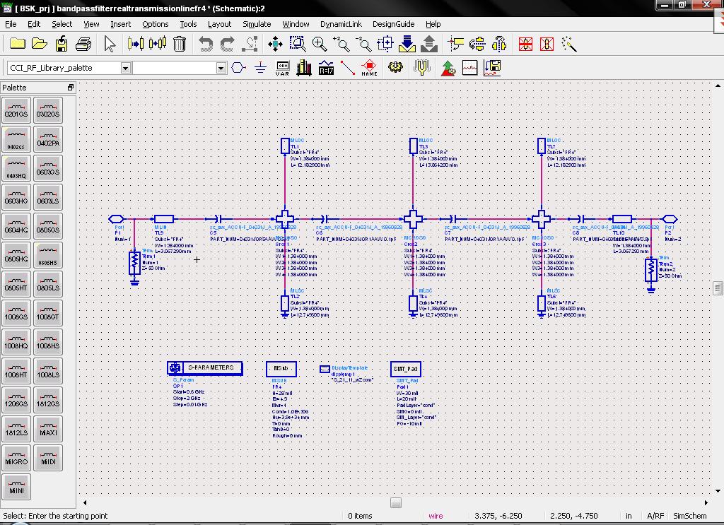
Because you have three coupled line that you modelled as three independent transmission lines?
how can i reduce this coupling effect?
In addition to the coupling, you have simulated without substrate loss (tand) in the schematic. FR4 is pretty lossy and with this narrrow band filter, the substrate loss matters.
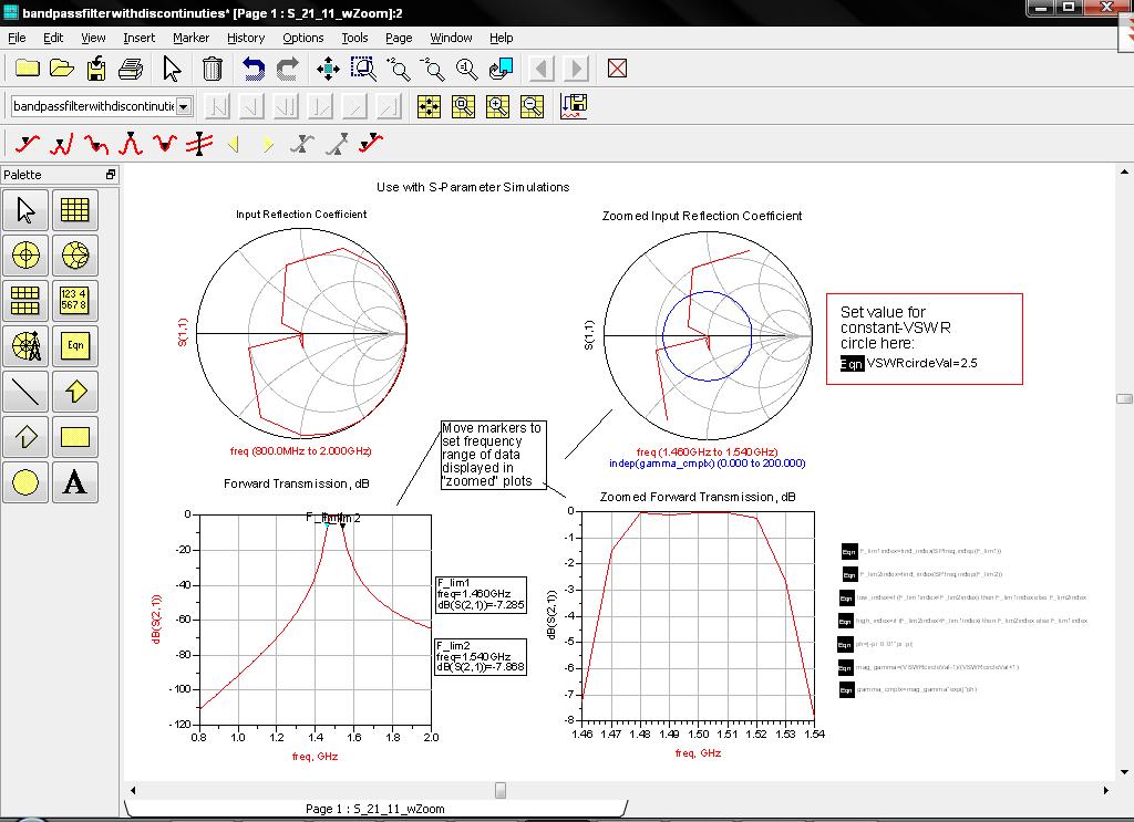
Well, one way would be to space the three resonators apart by using a short length of microstrip line. One class of filters uses quarterwave sections between the resonators as "unit elements" or "Richards Transforms". Of course, you have to re-optimize the filter parameters.
If you can not stand the increased overall width, you can splay out the resonator on the left to look like a >, and the resonator on the right to look like a <, with the closest being where the three chip capacitors are. Since the electric field is highest on the top end, you can keep e-field coupling down by moving the open circuited ends apart. And since the mangnetic coupling will be strongest where the magnetic field is strongest at the short circuited ends, you can minimize magnetic coupling by keeping the three short circuits apart.
Or you could just live with the coupling, and simulate it properly.
Thank u very much. I will try to seperate resonators.
Hi I am interested with building a 1.5 GHz filter. I have seen your circuit which gives very good results. What are the part numbers of the capacitors. can you send me the schematic file you have? Also are these capacitors available in the market? It seems that the theory of micro-strip filters is little bit complicated. Any help will be appreciated.
Thanks
Yes it gives very good results but when simulated in EM simulator it does not give good results or i cant get :) yes components are real avx 402F series.I am dealing with the layout of the filter.Components that i used in this filter are +-0.05pF so they are really good for RF/MW design.I attached .dsn file if u know how to optimize this layout for EM simulation please inform me.
Thanks very much Alpuslu. I will have a look to it. If It suits my application can use your design? I though the design of filter is an easy thing if I used ADS design guide, but the discrete components generated by ADS are very small and might not be available in the market.
Anyway Thanks
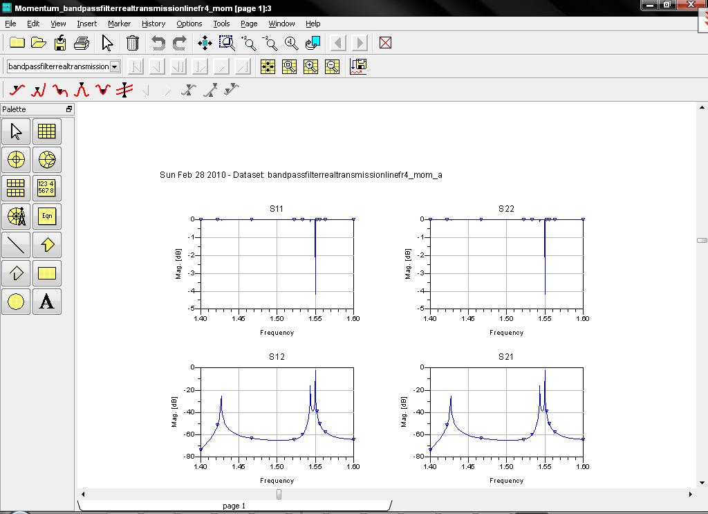
Your simulation looks so good because you have not include the substrate loss (Tand) in the simulation.
There must be a coupled Micrstip line model in ADS. I recommend you use that o capture the coupling at schematic level. As everyone else says, you need to include the dielectric loss in your simulations as well to get more accurate answer.
Actually i want to decouple these lines because they are independent transmission lines.I tried to splay out but i could not get sufficent results.I think i have to change the filter topology.Even without substrate losses i could not get sufficent results.