why S11>1 at 3.8GHz not at 1.9GHz oscillator design need help
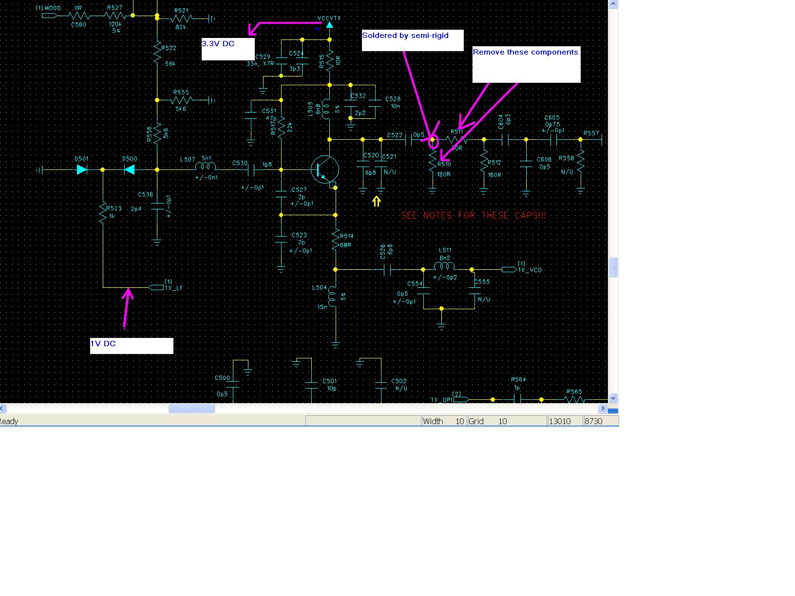
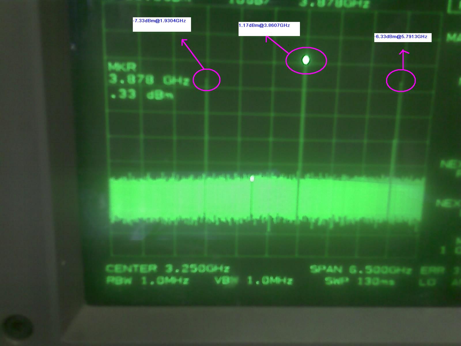
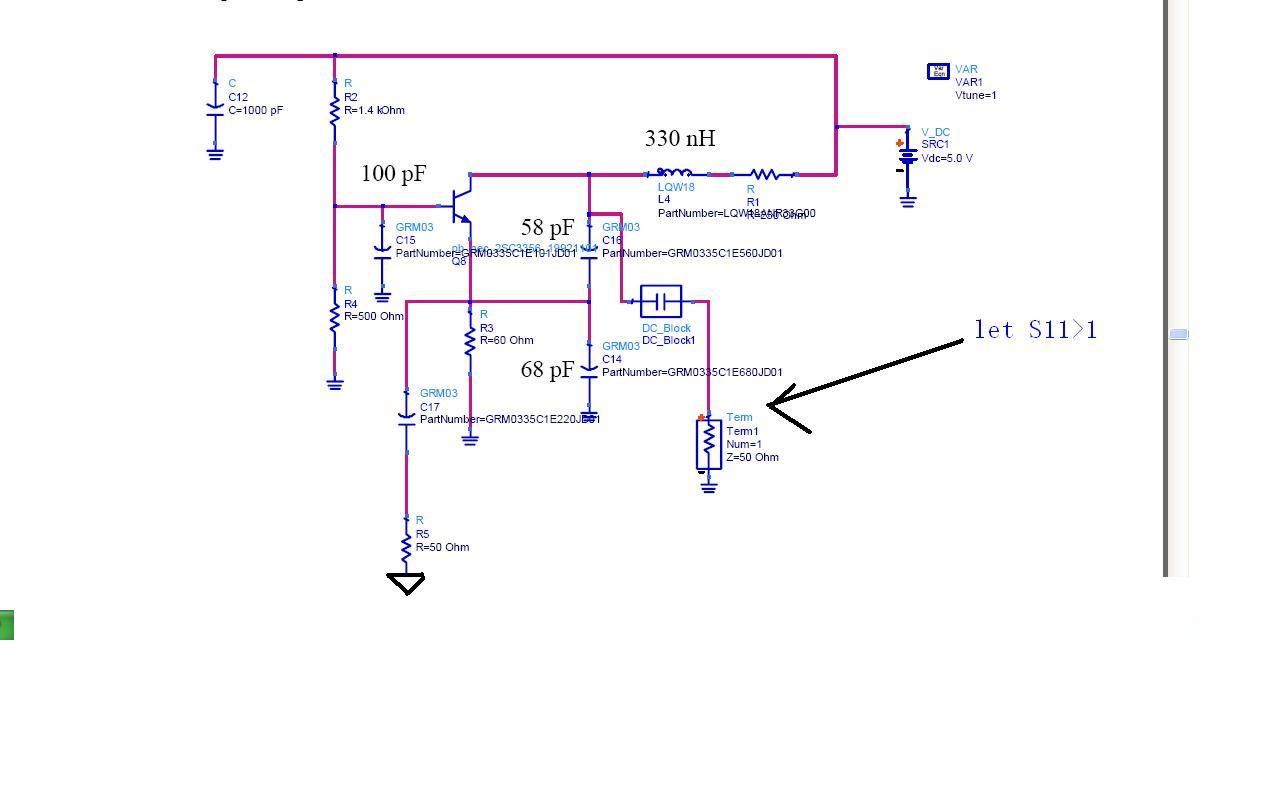
I got a 1.9GHz VCO(modified colpitts) demo board.As we know,we should let it S11>1 at 1.9GHz,but when i measured it(by SA and VNA),i found the highest power level is 3.8GHz at SA,and S11 seem >1 at 3.8 GHz.Whether it mean the oscillator is 3.8 GHz oscillator, not 1.9GHz oscillator?
Attached the schematic and photoes.
Thank you,
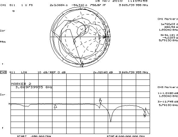
You can not measure S11 of an oscillator.Because the oscillator signal will interfere with VNAs signal and creates some beats.Only loadpull measurement gives you an idea about oscillator output impedance otherwise you should not connect the output of an oscillator directly to the VNA, it's dangerous.
And also, a VCO of 3.8GHz doesn't have any harmonic at 1.9GHz.So your oscillator works 1.9GHz but because of some design/measurment arrors you see a higher level at 3.8GHz which is 2nd harmonic of 1.9GHz..
Output filter may pass 3.8GHz only..Check this..
How can i tune oscillator circuit alone(if i design oscillator circuit)?Especially new design and the oscillator does not work.Any tip about the oscillator measurement by SA or VNA?
You can add a buffer amplifier, then you can use SA to measure osc.
Thank you for reply.What i want to find a way convenient to tune oscillator to work as attached simulation(let S11 of operating frequency greater than 1).connect directly to VNA,it is easy to find which frequency S11>1,but it is ideal(it is dangerous to break VNA). Any practicable way replace this ideal one?whether add a buffer amplifier can do it?And any friends share your experience about tuning oscillator?
What are you gonna do S11 ? It doesn't show you that the oscillator works well or not ...
If you would check the loop gain and loop phase, this is not the way of doing.You should cut the feedback loop and put a OSC Probe and check the gain and phase to see the Berkhausen criterias are satisfied or not..
You probably confuse negative resistance oscillators and you expect to see S11>1 but it's not correct.The point where you would to simulate is not the right point, you have to watch this input Refl. Coeff. from via resonator's eye...
If you load the resonator with 50 Ohm, you'll probably see nothing or a wrong number..
S11 measurement gives only a rough idea where IS POSSIBLE to oscillate the circuit (but not mandatory).
A Spectrum Analyzer is the option to measure and tune an oscillator, looking for fundamental and harmonics in the same time.
The signal level at the SA input should be low enough to do not make intermods at the SA front end (seems that your levels are too high).
If you get intermods, signal power measurements will be wrong, especially harmonics levels. You can place a 10dB pad attenuator at the output of the LO.
The buffer (which can be an emitter or source follower) could be placed at the point of the oscillator where you pick up the output signal.
Thanks for all kindness.The circuit is 1.9 GHz VCO.The aim is to get the trinal frequency-5.8GHz.What my task is simulate it as demo board reference,then measure.what is the first step when i simulate oscillator?