Best way to measure 1 dB Compression
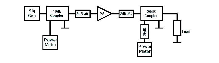
I am trying to measure 1 dB comp. point of a PA at 10 GHz. Our network analyzer's power range is not enough (up to 5 dBm) to measure it.
I use signal generator + spectrum analyzer to measure it. But, the output power of the signal on the Spectrum analyzer is changing if we play with the span, resolution bandwidth, reference power level and so on. Also if we change the input power from -30 dBm to +25 dBm, the signal level on the spectrum analyzer is not changing linearly even we do not change any setting of the spectrum analyzer.
Thats way which is the best method to measure 1 dB compression level?
1) Network analyzer (if we have enough power sweep range)
2) Signal generator + spectrum analyzer
3) Signal generator + power meter
thanks for your advice...
Option 3 would be the best. Usually power meters are very accurate.
Yes, power meter will be the best , I agree.
So what will be the method if we use only one power meter?
First extract the losses of the cables and limiters and after that measure the PA... It will be accurate enough, I think..
For P1dB measurements you can use just one power meter. Have to measure first the output loss (between PA output and Power Meter input), and set the power meter offset reading for this loss. Start with low input power from SG, and increase the power until PA output power compress with 1dB. Have to use 0.1dB steps on the SG.
If you use a power meter make sure your amplifier doesn't produce any high level harmonics or spurious terms at the power meter sensor as the power meter will include the power of these in the readout.
When measuring P1dB, the amplifier surely will produce harmonics or spurious. But if the harmonics are -20dBc below than carrier, the result is only 1% influenced.
This is the whole idea measuring the P1dB. To see the point where nonlinearities starts to appear.
Then it will be best to include a high order band-pass filter between amplifier output and power meter to suppress the high order terms...
Better than a BPF is to use a LPF, which can get better and wider rejection, and lower inband insertion loss, for smaller size.
It is true that LPF will have smaller size and lower in-band insertion loss but I did not get the point for better and wider rejection ...
Is it because of the high order ripples in the stop-band of high order BPFs..?
I doubt it will 'surely' produce harmonics at the power sensor because I didn't know if his amplifier already has a roofing low pass filter built in to the design. (That's why I specified harmonics 'arriving at the sensor')
However, if it doesn't have a filter it may produce harmonics that are very high eg -10dBc. These will influence the measurements and can give false results when trying to compute efficiency etc.
But, at frequencies above 10GHz the power meter sensor may not have a flat response any more. i.e. the sensor might give a false reading of any large terms that lie outside its range.
A LPF can reach easily 10GHz in stop band, when BPF hardly can get this range (due to multiple internal resonances).
Today even relative cheap power sensors have flat response up to 18GHz.
measure dB Compression 相关文章:
- How do I know if a spectrum analyzer is enough to measure an specficic DAC?
- Using ADS2019, How to set and measure tempature values for LNA?
- H field measurements with waveguide twist
- How can I measure the Side-Band Amplitude?
- Keysight PNA Harmonics measurements
- frequency shift between simulation and measurements