q3d subckt
I've build a model in ansoft Q3D,when the simulation is finished,I right click Analysis to export the equivalent circuit, the format of the file is *.cir.
The problem is I don't know how to use this *.cir file in ansoft designer or other softwares,so I can see how the quilvalent circuit is and do some comparison with the results of HFSS.
Any advice would be helpful.
LTCC
i think the .cir is a spice format , which is a spice netlist file . so u can open the .cir file with a wordpad or any text editor , and then draw the circuit on the designer
khouly
Thank you for Khouly.
Isn't any automatic way to do this?
check the circuit dropdown menu in ansoft designer , and try to import it as a model , netlist file
i am not sure if this work or not ,
but i have ADS u can easily import the file and convert it to schematic
khouly
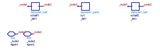
The following is the content in *.cir file.But I don't know what the nodes in the subckt segment stand for,such as 0,1,2,3,4.Would you help me to draw the circuit?
* BEGIN ANSOFT HEADER
* node 1 Box1:Source1
* node 2 Box1:Sink1
* Project: via_gsg
* Format: Ansoft Designer
* Topckt: viaModel1
* Left: 1
* Right: 2
* Creator: Ansoft Q3D Extractor 6.0
* Date: Tue Jul 10 19:50:02 2007
* END ANSOFT HEADER
.subckt viaModel1 1 2
XZhalf1 1 3 viaModel1_half
XY1 3 viaModel1_parlel
XZhalf2 3 2 viaModel1_half
.ends viaModel1
.subckt viaModel1_half 1 2
V1 1 3 dc 0.0
R1 3 4 0.0083728141
L1 4 2 8.2601859e-010
.ends viaModel1_half
.subckt viaModel1_parlel 1
C1_0 1 0 5.081879e-013
.ends viaModel1_parlel
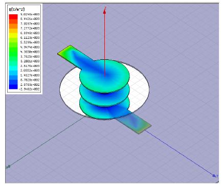
This is the model I built.
Thank you so much for khouly, taking your advice,I make another try.
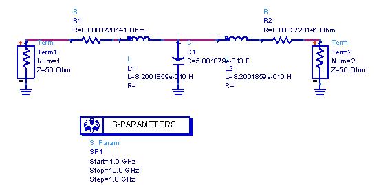
I have imported the *.cir file to ADS, and make the comparison with the simulation in designer which contains the Q3D design as a subcircuit.
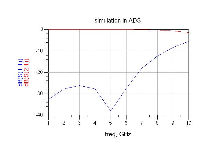
But the two simulation results are different.
The following is the imported design in ADS and two simulaiton results:

i see that u make ADS simulation ,but the results from the designer
where are the ADS simulation result
khouly
The last graph is the comparison of the two results and you can see the column in the right,it saied simulation in ADS,the blue one is S11 in ADS.
The following are two simulations dividually in ADS and designer.

Can anybody help me? Thank you!
it is strange , how two inditcal passive circuits , give different simulation results
khouly
you can use the *.cir file un PSPICE of cadence, it is a netlist, it is just the subcircuit containing tha SPICE equivelent circuit of your model. but in Q3D you can also change the the export file to other extentios, if I remember well you can exporto to RLC circuit model, and some others. what do you need the circuit for? to compare the results with HFSS? in HFSS you can also export the circuit and use SPICE to simulate. hope this helps.
please someone explain how to extract the circuit model of HFSS result?