I want know which modulation is used. (AM or FM)
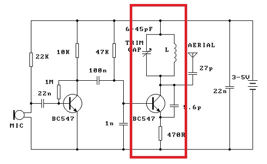
In the picture this circuit is wireless microphone and boxed part is 100MHz oscillator. audio signal is amplified and then modulated from this oscillator.
help me.
Exactly, operating frequency is FM band and this circuit is FM Transceiver. but I can't sure that It is FM modulation.
I think it's AM,"Collector Modulation Method"...
neither is used
this is a phase modulation circuit
similar to FM so is still decoded by a FM demod
sound's different in AM receiver than FM mode
and this is why its used
fm is mostly hard to hear using a simple receiver {diode coil and earpiece}
PM is easier to decifer using AM receiver
its also a bad design for a bug better to use low power fet's
this design is also very lossy.. for a bug
a bug should be as efficent as possible and this way it lasts a long time
so fast answer~
Thanks a lot~[COLOR="Silver"]
---------- Post added at 15:27 ---------- Previous post was at 15:17 ----------
---------- Post added at 15:29 ---------- Previous post was at 15:27 ----------
Thank you for your clear answer.
But I'm Korean and I don't know the word 'decifer'
and you mean that receiver should be AM method?
KAMSAMIDAAAA, and A-ni-e-yo Mr,kywous.... :)
Decipher : In (Electronics & Computer Science / Communications & Information) to convert from code into plain text; In simple words it is "decode"
Could you explain why it is PM? I would have thought it was AM modulation. Surely the signal from the Microphone is being injected into the base of the oscillator whereby it alters the gain of the oscillator, thereby Amplitude modulating the oscillators signal.
If you use a Spice simulator you will see that this circuit have a little bit from all modulations, AM, FM and PM.
The modulation type depends very much by the audio level.
I also don't understand the classification as phase modulation. The poster is correct about equivalence of PM and FM. PM baseband frequency characteristic is however different, and a generic phase modulator looks quite different from the shown circuit.
Many simple "FM" transmitters are build like the shown circuit, a lot has been shown at edaboard before. They are of course generating AM, but FM, too. Simply, because modulating the oscillator bias changes the transistor junction capacitances and thus the oscillation frequency.
phase modulation = adjust phase frequency stays the same just the freqencies phase relation ship to last changes over time
when you pass audio the phase output changes any base
so no emphasis is needed unlike fm for clarity on fm receiver
current and voltage 'based' where you have both you also have resistance
where all three change you also have capacitance and inductance
its a (((6~5~4))~(3*2))) = 1 where ladder ratio 1= voltage 2 = current 3 = resistance 4 = capacitance 5= inductance 6 = reactance
so its realy a 'reactive frequence phase change '
gives am fm and pm also cm {conical modulation}
frequency modulation= actual frequency changes + - usualy voltage 'based'
this is actual audio frequency input independant its the preemphasis set it
am = amplitutude of a given frequency changes with respect to the audio modulation input usualy only current 'based' sometimes modulated voltage but still the current dictates output rf level
the tank circuit sets the frequency {on collector on the driver transistor 2}
the oscillator driver transistors is phase modulated by the audio
transistors adjust phase by 180deg relative to the input
but can modulate an rf circuit + - 45deg (min/max}
as phase modulation
some here seem to act as if you never come accross this you should know this from teaching and study
infact its very common in low power circuits as you can demod it overall better with all circuits
some resonator type bugs made from just two tubes of metal use the same cross phase system
the amplitude will also change just a little
so yes its a bit of all
but is known as phase modulation
as phase relationship
incomposes all three components
yes even its own phase matters as capacitace latency dictates
becouse capacitance changes even of a transistors depletion layer
with different freq input
the am componenet is why it sound slightly more inteligable on simple receiver
as i posted
nice topic
old hat...
better these days to use rf spray
then it forms a molicule it responds when dry and transmits audio
or even 115k data or usb data just spray it on the socket
over 1km
spray on target walk away
you just need to transmit a carrier energyser
the molicule resonates and provides the mix output
you receive it on the if
use audio techniques as back up collector
like audio antenna using tunes copper tubes layers
reverse organ pipes as a group
you can hear someone talk in audio 2km way line of sight
rf is only good for a building
rf spray works thru walls with atleast 200m range...
and has no mechanical mic so can 'hear' anything you can amplify up!
so be warned... rfsprays now are indelible and tunable over time {slowly drift} etc etc
built in charicteristics
lasts 10,000 years and are lately delible on rf send ... so you can erase them
fragment then they simply blow up the molicule by rf pulse emp
even this is now old hat...{reform .... etc}
best write secret/sensative things down and dont talk at all
then eat them so rice paper and a pencil is handy
till spray camera is working {it is already}
get real with bugs... they are everywhere... for sure
dont bug study them and build a receiver and rf driver source these days
and tune in the sprays have no taist and no smells and dont set off alarms known
who knows but james bond etc...
the americans leave it everywhere...
by far the best policy is open
and live your life without secrets...
.1mm X.1mm of these molicules or < < less
can transmit all your companys data over 200meters from the chip pin .. etc
rf chips are also a problem here as they can clone data and repeate it over several packet nodes even arrays or memory can be read .. this way
i dont trust rf chips
where there is one freq harmlessly outputing your tracking data
there is another node receiving all data emil etc etc from around
spy chips
for sure! is whats not new now ive posted it .. even 5 years ago this was old hat...
so best way is not to even think these days
im sure more each day a think spray has been made
that can imprint thought as well as read thoughts...
who knows
its all possible easy with very old tech now <1970 molicules maker machines
{common in units just type out the molicule you want and print it}
The long-winded explanation doesn't change the fact, that changing the bias point of a real oscillator actually changes the frequency in contrast to phase modulation where "frequency stays the same". If you have been using this circuit, you'll know about.
If you analyze the base band frequency characteristic, you'll notice, that it's corresponding rather to FM than to PM.
In fact this modulator has more PM than FM component.
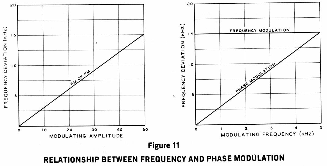
In Phase Modulation the frequency deviation is a function of the amplitude AND frequency of the modulating signal (left picture).
In Frequency Modulation the frequency deviation is a function ONLY by the amplitude of the modulation signal (right picture).
Most of the NFM (Narrow FM) modulators part of the old commercial two-way radios use Phase Modulators, and they use circuits similar to the one in discussion.
Phase modulators allow getting narrow bandwidth than frequency modulators, which is fine for voice communication.
I don't think so. For the orignal circuit, I see in a LTSPICE simulation with 0.1 Vpp modulation input
- 5% AM
- 800 kHz FM
- < 10° PM
So please calculate, above which modulation frequency PM will be dominant.
I'm also waiting for a graphic explanation, how the said oscillator circuit should generate considerable phase modulation.
modulation FM 相关文章: