Please tell whether it is right
Well is the characteristics good when compared to a filter.Actually i optimised the structure so much and finally arrived at this output.My application is to make the structure to behave as a filter.Please advice.
well.. please dont joke my friend..Well this was the result i got when i simulated the filter structure...is the simulation result fine when compared to a filter chara...
What kind of filter are you comparing this desgin against?
What are your design targets? Bandwidth, frequency range, cut-off frequency, rejection, etc.
Depending on your requirements, you should be able to self-analyze and compare your metamaterial structure's performance against the specs (or performance of a similar component/filter).
what if when compared to an ideal or a general filter
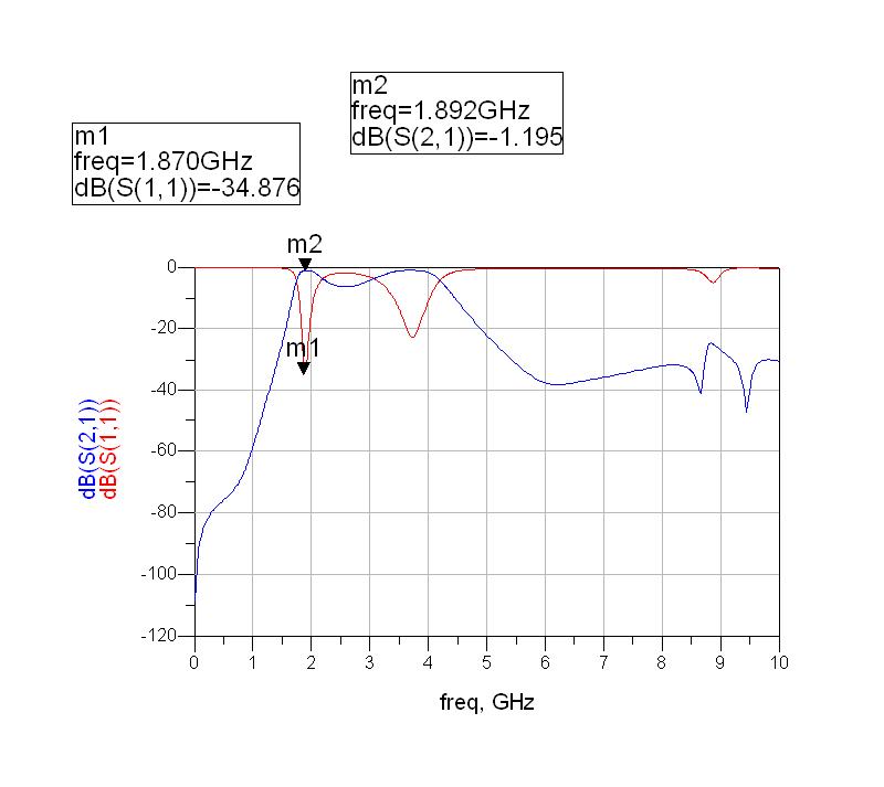
the s21 performance looks bad between the two dips of s11. about 20% of the signal would be transmitted in that band which looks like it should be a rejection band. but as people above mentioned, it all depends on your requirements.
What is a general filter? Lowpass, highpass, bandpass, notch, Bessel, elliptic..... there are MANY filter types, all of which have different performance characteristics.
From your plot, I'll guess that you wanted to make a bandpass filter, center frequency around 1.9 GHz, with a bandwidth of approxiamtely 0.2 GHz (1.8-2.0 GHz passband). In that case, your loss isn't too bad in the passband (~2 dB), and return loss is good (better than 20 dB in-band).
However, your high-side rejection is terrible up to 4.5 GHz. You'd get a lot of out-of-band signals coming through from 2.0-4.5 GHz (especially around 3.6 GHz with only a few dB's of rejection). The low-side rejection looks ok with a steady rolloff. Also, your high-side rejection is limited to around 30 dB, which is poor when compared to a printed filter of similar design (1.9 GHz bandpass).
well enjunear....what i wanted is a band pass filter...so what do you think about the characteristics...well i need to fabricate the structure and have to compare with this result...Wat do you suggest.....actually i am workin on metamaterials.....do respond
As I had detailed in my last post, this isn't a great bandpass filter. Mostly because you have two regions with relatively low (<10 dB) insertion loss. You really need to set some goals for your design, then evaluate your progress based on how your design meets those goals.
Here are my suggestions:
1. Define the bandpass filter passband frequencies (hint: mayb 1.8-2.0 GHz)
2. Define the maximum insertion loss in the passband (hint: better than 2 dB)
3. Define the return loss inside the passband (hint: better than -15 dB)
4. Define the out-of-band rejection (maybe >40 dB rejection @ 1 GHz from edge of passband, and >60 dB at 2 GHz+ from the edge of the passband)
If you think the design is good enough to fabricate, then fabricate it, and see how you model meets reality. If you are designing this to be a useful filter, then I would say you need to find a way to improve your rejection above the passband. The low-side looks like and bandpass filter roll-off, but the higher frequency side does not.
hey enjunear...i have been optimising my layout for a long time but getting results like this...shall i forward you my layout.are you familiar with ads momentum since i am using that to build.If so just pass me your id so that i will send it.Hope you understand my state
I don't think I'll be of any help on this problem. I've never designed with metamaterials, I'm just an RF designer with some background in what filters are supposed to look like