Antenna Measurement impacted by Coax Cable
I have to measured antennas in terms of impedances and radiation pattern of a module containing transceiver and antenna.
My concern is the impact of the coax cable as that is in the real application not there.
What are your recommendations?
Regards,
WW1
Shorter coax cables works better than longer ones, in terms of impedance change or signal attenuation,
Thicker coax cables have less attenuation than thinner ones,
Good quality coax cables works better than low quality ones.
The coax shielding is different from cable to cable. Better the shield, lower the radiation.
Coax flexibility is good to have, but generally very flexible cables don't keep the impedance constant as the rigid ones.
as vfone said , there are many table that lists many type of practical coax cable and you could search them on web.
Does someone has further ideas?
I am more concerned about the change in ground referece through adding a cable to the setup.
Regards,
WW1
Yes I do that sort of measurement all the time.
You can not, in any way, attach a cable/signal generator to a small wireless module without dramatically changing all of its antenna characteristics. The biggest problem is that you are significantly adding to the effective area of the board's ground plane. Many wireless units have very small antennas (much smaller than quarter wavelength) and correspondingly too-small ground plane. It is the combination of the small antenna and too-small ground plane that is the crux of what you are trying to measure. You want to know the radiation pattern of that exact combination inside of the same package the unit will be mounted in.
So, adding the cable will at the minimum:
1) change the resonant frequency of the antenna
2) change the radiation pattern of the antenna, since there are significant RF currents now running on the outside of the cable shield.
But, never the less, one needs to measure these devices. Some things you can do:
Invest in a big bag of ferrite beads:
20 Clamp-On Ferrite EMI-RFI Suppressors - eBay (item 330519446693 end time Mar-15-11 13:13:24 PDT)
On a 3' cable, I might have 6 of these things clamped on. This is probably the only way to get an actual VSWR measurement of the antenna. Try to get ones with the hole just slightly bigger than your cable diameter--the snug ones seem to work the best.
Have the software re-written so that you can get a CW tone out of the unit while in "test mode". That way you can take the exact same physical hardware, and rotate it on an antenna test range, to get an antenna radiation pattern.
If you can not do that, you might be able to get a very small oscillator chip, solder it onto the board somewhere, and get it to feed the antenna instead of the normal circuitry (using the unit's internal battery of course!). This works best if there is a buffer amp in the unit already, so that you can feed the input of the amplifier instead of the antenna directly.
If you are trying to fine tune the resonant frequency of the antenna, if you can reprogram the software with a cw sweeping tone, you can stand off with a broadband antenna and see where the received power peak is in frequency. You then adjust the board's tuning components until that power peak is in the center of the sweep band.
Obviously, if you can plan in these software "test modes" during the intital design, you life at first article test will be easier.
Good luck.
Rich
Any impact of the coax cable is depending on a lot of factors. If DUT have a ground plane that is short compared to actual wavelength or if the antenna not is well balanced or in case of high VSWR, then can measuring cables be very active part in both resulting radiation pattern and measured impedance.
Time delay due to added cable length and cable impedance must also be compensated for, to be able to measure real impedance. Use a good calibration kit to compensate for measurement cable. Ferrite around coaxial cable, full symmetric transformer or balancing chokes are some of the tool that can be needed to reduce impact of added ground loops due to measurement cable.
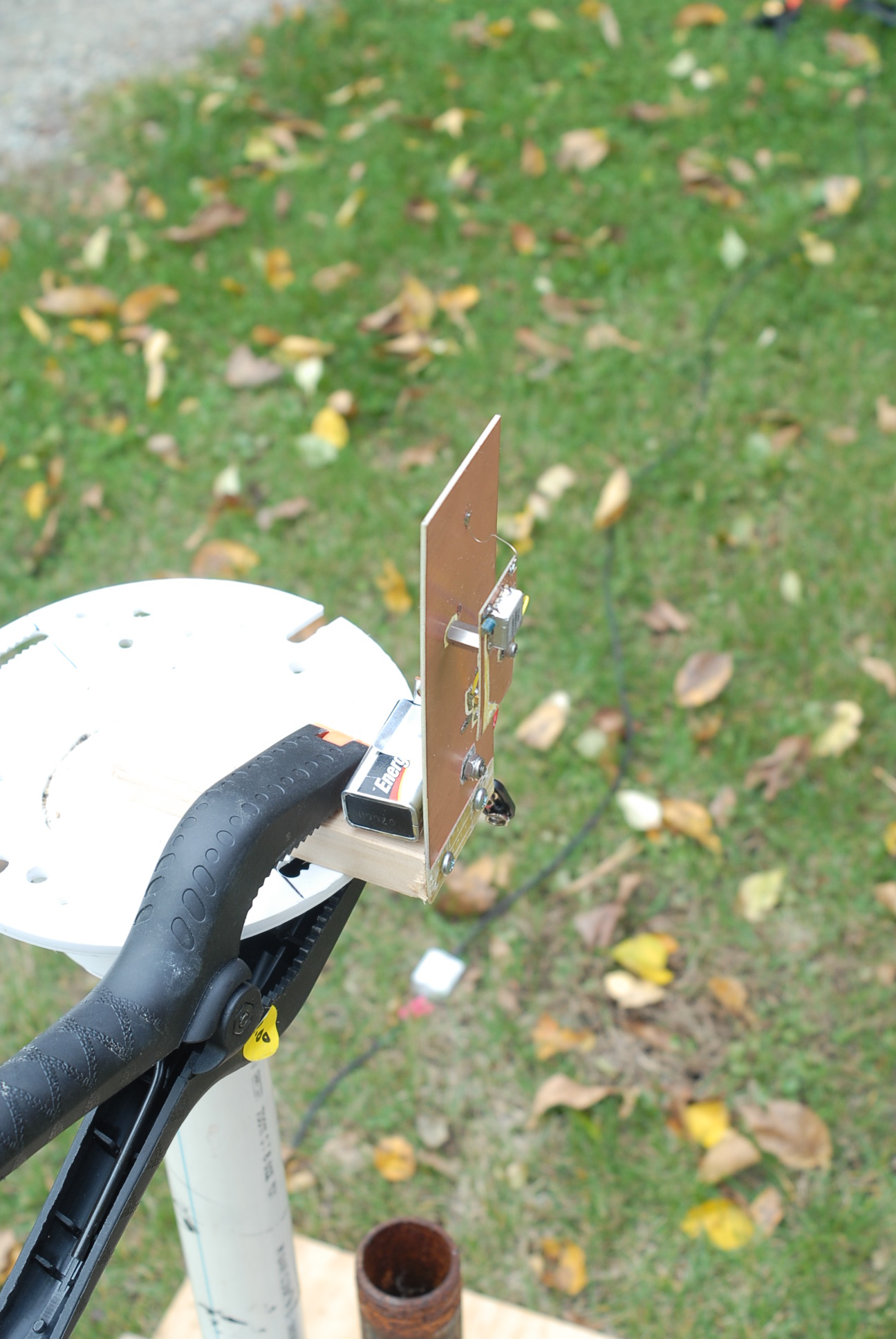
Here is an example of such a test. Had to choose between 6 different types of "short" antennas for a wireless job. I knew the approximate size of the mother board, and the approximate size/shape of the RF daughter board.
I took a piece of FR4 and simulated the motherboard and the battery pack. I then made daughter boards with a minicircuits vco, and the various antennas attached (one at a time). VCO was CW at midband.
I was able to sweep the azimuth 0-360 degrees, and the elevation from horizontal to vertical. From the data, I could figure out which antenna had the broadest radiation pattern, and had some data with which to compute the link budgets with.

Rich
Nice setup, but probably is not indicated to sit on the blue garden chair, during experiments, when enjoying a glass of bourbon
Yes, that IS their intended function. Antenna pattern testing can be thirsty work!
Measurement Antenna impacted 相关文章: