PIC16F877A UART interfacing problem
so later i simulate in proteus with simple schematics to check the functional of my code (2 PIC16F877A)
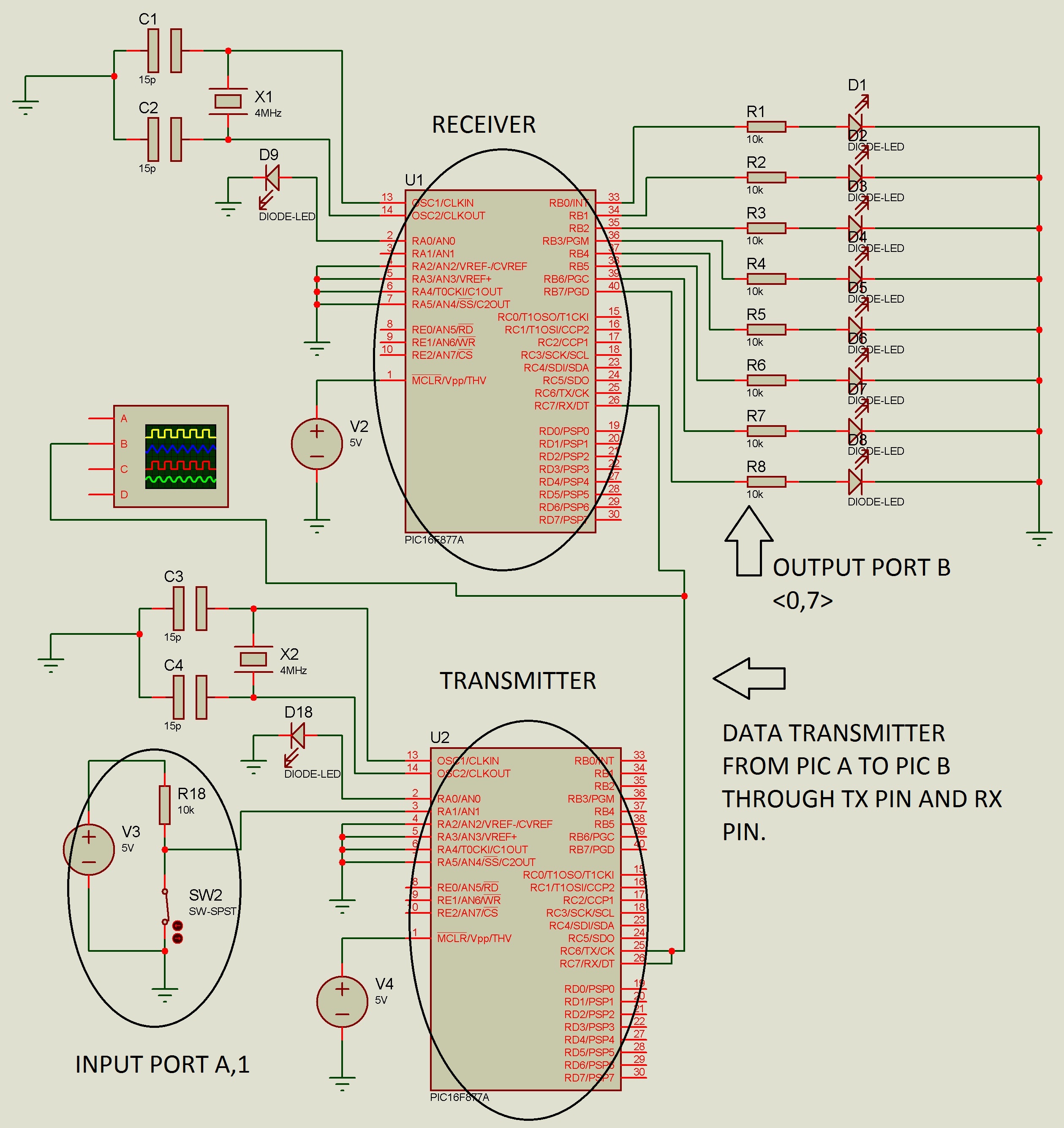
PIC A (Transmitter) - with several pull resistor in PORT A
PIC B (Receiver) - With 8 LED to display the byte received from the RX pin in PIC B
* PIN TX from PIC A is connected with PIN RX at PIC B to complete the circuit. (Ignoring the RF module)
Thanks ***, the simulation is working. But it doesnt work when i construct the hardware.
The output from receiver (PIC B) doesnt show same as the transmitted byte. The LED show various output ( 8 LED keep Blinking randomly ). My question is as below:
a) Is that external circuit or IC to add before RX pin in order to receive a pure signal. ( such as filter, or any IC )
b) Any good programming code that it is work in software and hardware.
c) Any project that is relevant to my project.
Below is my sample code (I send Char '[' to check the a valid byte)
PIC A Code (Transmitter)===================================== ============
__CONFIG _CP_OFF & _WDT_OFF & _XT_OSC & _LVP_OFF
MAIN
;HARDWARE INIT
BCF STATUS, RP0 ;
BCF STATUS, RP1 ; Bank0
;=======BANK0
MOVLW B'10010000' ;enable receive and serial port
MOVWF RCSTA ;write to reg
BCF PIR1,RCIF ;allow next byte to be received
;=======BANK1
BSF STATUS, RP0 ; Bank1
MOVLW B'00100000' ;enable transmit and low baud
MOVWF TXSTA ;write to reg
MOVLW D'51' ;(Fosc/(64*desired baud rate)-1)
MOVWF SPBRG ;Write to reg
BCF TRISC, 6 ;Make RC6 as output for Tx pin
BSF TRISC, 7 ;Make RC7 as input for Rx pin
MOVLW 0x06 ; Configure all pins as digital i/o port
MOVWF ADCON1
MOVLW B'11111110'
MOVWF TRISA ;Tris port A as input
CLRF TRISB ;Tris port B as output
;=======BANK0
BCF STATUS, RP0 ; Bank0
BSF PORTA,0 ;Microcontroller On status
MOVLW 0x0
CLRF PORTB ;Clear port B
CLRF PORTC ;Clear port A
OVER
CALL DELAY10A
CALL TRIGGER_TX
BTFSS STATUS,Z ; transmit,Z=0
GOTO OVER ; Wait for portb on change
CALL TRANS
CALL DELAY10A
CALL TRANS2
CALL DELAY10A
GOTO OVER
TRANS;-------Serial data transfer subroutine
D1 BTFSS PIR1,TXIF ;wait until the last bit is gone
GOTO D1 ;stay in loop
MOVLW '['
MOVWF TXREG
RETURN
TRANS2;-------Serial data transfer subroutine
CLRF PORTB
D2 BTFSS PIR1,TXIF ;wait until the last bit is gone
GOTO D2
MOVLW 0X18 ;save port A byte to wreg
MOVWF TXREG ;transmit port A
RETURN
TRIGGER_TX;------- test if we should transmit or no
CLRW ;clear wreg
MOVLW 0x03 ;Test active port A pin 1
XORWF PORTA, W ; port A to be tested, send if pin1 is activated
RETURN
PIC B Code (Receiver)======================================== =========
MAIN
;HARDWARE INIT
BCF STATUS, RP0 ;
BCF STATUS, RP1 ; Bank0
MOVLW B'10010000' ;enable receive and serial port
MOVWF RCSTA ;write to reg
BCF PIR1,RCIF ;allow next byte to be received
; BSF INTCON,PEIE ;enable peripheral interrupt
; BSF INTCON,GIE ;enable global interrupt
BSF STATUS, RP0 ; Bank1
; BSF PIE1,RCIE ;set RCIE interrupt enable
MOVLW D'25' ;4800 bps (Fosc/(64*desired baud rate)-1)
;baud rate error (cal. SPBRG - D)/ (D+1)
;baud 1200 = 0.16% error; D=51
;baud 2400 = 0.16% error; D=25
;baud 4800 = 0.16% error; D=12
;baud 9600 = 8.51% error; D=5
;baud 19200 = 8.51% error; D=2
MOVWF SPBRG ;Write to reg
BSF TRISC, 7 ;Make RC7 as input for Rx pin
MOVLW 0x06 ; Configure all pins as digital i/o port
MOVWF ADCON1
CLRF TRISA ;Tris port A as output
CLRF TRISB ;Tris port B as output
BCF STATUS, RP0 ; Bank0
BSF PORTA,0 ;Microcontroller On status
MOVLW 0x0
CLRF PORTB ;Clear port B
CLRF PORTC ;Clear port A
OVER
RCV
D1 BTFSS PIR1,RCIF ;check for ready
GOTO D1 ;stay in loop
MOVLW '['
SUBWF RCREG,W
BTFSS STATUS,Z
GOTO OVER
BCF PIR1,RCIF ;allow next byte to be received
D2 BTFSS PIR1,RCIF ;check for ready
GOTO D2 ;stay in loop
MOVFW RCREG
MOVWF PORTB
MOVWF MRX_BUFFER
BCF PIR1,RCIF
GOTO OVER
Thanks for the helps
a) it have to be TTL level, so you need amplifier with limiter
b) ages ago, when personal computers had tape recorders to store data, was plenty examples of cose
c)google ZX sinclair
There are a number of issues I'd comment on here:
1. You can't simulate an RF connection - you must do it in real world
2. There is no reason to use assembler for this project - if you use C you will get more help - if later you find you must have assembler hand code for it - you can add that part in wwhere its required. But I doubt it is needed here.
3. Without a good deal of knowledge about the RF design you are using it's
pretty much impossible to advise - for example - what sort of antenna are you using? (Whip, coil, loop or whatever) is it physical or PCB
where is it placed in relation to everything else - what about ground planes?
What transfer protocols are in use what about buffering, interrupts and data collection and so on.
If you are using someone elses RF module which one - have you followed "suggestions" from the manufacturer exactly - what frequencies are in use that
might be interfered with from external sources (your next door neighbours TV transmitter for example - or your own RF mouse etc)
RF projects can be tricky at the best of times - to help with one really needs
you to supply much more information.
If you can identify the area that is giving you the problem you may be able to get some practical suggestions but the code is probably the least of your problems. Don't rule it out but RF is generally the fragile part.
You might isolate it by using a hard wired link to verify some things first. Then you'd at least know if its more likely to be an RF issue or not. (Especially given the error you report)
jack
As suggested, try it with a wired connection first. There are other considerations, you probably want to add some kind of identification to make your data distinctive so you don't decode someone elses transmission.
Your biggest problem will be encoding the data if that isn't done in the RF modules for you. The encoding isn't for secrecy, it is there to equalize the number of 1s and 0s in the data stream so it's average is zero. It's a bit difficult to explain why this is necessary but if you Google for "manchester encoding" it will explain the reasons. There are alternatives to Manchester but they all basically aim for the same outcome.
Brian.
Thanks for the suggestions. But it will help much if you include some example of amplifier for PIC16F877A or circuit for my project.
Thanks.
---------- Post added at 12:42 ---------- Previous post was at 11:36 ----------
Thanks 123Jack, here is roughly info about my RF module. i order the RF module from Cytron company. (Welcome to Cytron Technologies - Robot . Head to Toe : PIC Training Malaysia, PIC Microcontroller sure i had follow the suggestions based on the manufacturer including the source power and long of the antenna.
But in the project, i will ignore the RF module first. because i would like ensure i m transmitting my signal and receiving signal successfully on the PIC2. In order to made sure the transmitted didnt interference with the noise, so i would like to direct connect my TX pin from PIC A to RX pin at PIC B (without any ext circuit like buffer or filter in between them). So when i received the signal at PIC B (receiver) it show difference result (8 LED keep Blinking randomly ) . Do you have any idea about it. It might be my coding project or circuit problems.
---------- Post added at 12:54 ---------- Previous post was at 12:42 ----------
Thanks Brian,
Hi Joe
OK - If I understand correctly you have now hardwaired the 2 pics together
and get the same result.
What you are left with to debug is
1. 2 x PIC software (code in each chip)
2. 2 x hardwired interface cuircuits.
I can think of a few things that could cause problems of this nature
Sorry if this is too simple for you - I'm just trying to work it through -
First - check you have initialised both pics correctly. It is very easy to
forget something - PICs generally initialise in analogue mode so setting ports
to digital can be an issue - I see you are doing this but double check you have the right commands for the flavour of PIC you are using - (also I'm not very familiar with PIC assembler so I can't advise reliably on syntax - hence my C suggestion)
Also make sure your chips dont have port interrupts set where you don't want them and do where you do - I often forget to reset aftewr trying things and end up with a missconfigured port or something that way.
RC6 & 7 I think are sometimes connected to a PWM - make sure you are
configuring that correctly and have no timer interrupts running on them
(I dont have access to the datasheet here so cant look it up ATT)
...essentially just double check your chip and clock settings etc
Once you are sure you are sending the correct data - do the above for module B and then ...
I would then configre unit B to read 1 byte and display it on the LED's
(if you have an easyPIC6 or similar you could just set it to loop on this and press a button to get another byte or something like that)
the idea being to look for any specific pattern in the recieved data.
If the data truly is random - look for clock/noise/counters/interrupts missconfigured etc.
For the electronics check for things you may need like pull-up resistors on the ports - loose connections etc. If I remember correctly the 16F877 has weak pull-ups on one of its ports (PORT-B I think?) - double check the datasheet for configuring for that sort of thing.
I can't recognise anything to do with interrupts or handshaking in your code
relative to the amount of data you send - check buffering and handshaking if unsure.
Those are some things to try anyway - if you can convert to C code it may help to diagnose. (I recommend mikro-C Pro - the free compiler licence should be adequate for this I think)
Or if anyone has better PIC assembler skills than me perhaps they could chime in here...
jack
Thanks Jack... thank you for your idea.
I will try your idea soon. but now i would like to share my circuit to you all first so that you all can understand my circuit. btw i need someone to give some advise on my circuit.
hi joe
sorry
perhaps someone else can help with that - for some reason my
firewall refuses to allow elektrodata.net to display the full size images
(Not just your post - everyones) even if I manually configure.
jack
Put a resistor in series with D9 !
The circuit should work. I assume you have placed decoupling capacitors across the supply lines and followed good layout practice around the crystal and its capacitors.
Personally, I would have used the receive interrupt to tell when a character has arrived, it is easy to do and it saves you from sitting in a software loop while waiting for a byte to come.
Brian.
This link might be help
PIC microcontroller serial communication tutorial
Thanks for the suggestions. But it will help much if you include some example of amplifier for PIC16F877A or circuit for my project.
Thanks.