input impedance of RLC tank, and characteristic impedance
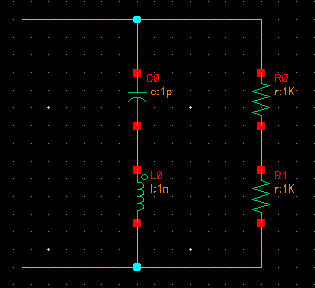
I have an RLC tank as shown in attachment (2R in parallel with an L and a C). I have two questions about it:
1) Why is the characteristic impedance of this LC tank sqrt(L/C) and what meaning does it have?
2) When computing the input resistance of this tank, what role should the characteristic impedance play?
Thanks.
There is one single frequency wo=1/sqrt(LC) for which the reactive conductance of the capacitor
and of the inductor (wC and 1/wL), respectively, are equal.
Now the answer to your question:
If woC=1/woL you can insert the above expression for wo and you get:
woC=sqrt(C/L) and woL=sqrt(L/C).
In words: The characteristic impedance is the impedance of both reactive elements for w=wo (resonant frequency).
For the present circuit (ideal L and C), Y would be inifinite.
I have corrected it already.
Thanks
LvW
LvW, thank you so much for your detailed reply. I suppose I was getting caught up in the definition of characteristic impedance as it pertains to transmission lines, but the math that you have described makes perfect sense. I am actually pursuing this problem as a way to calculate the input impedance of the circuit attached here:
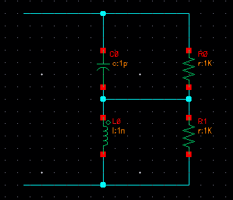
Using what you"ve described, I calculate Rin as 2R/[1+R/Z0], although...I have also seen it as 2R/[1+(R/Z0)^2]? I must be making a mistake somewhere in the calculation.
---------- Post added at 18:36 ---------- Previous post was at 17:43 ----------
Actually the derivation described above is all wrong. If you account for the +j and -j for the inductor and capacitor impedances, you will get 2R/[1+(R/Z0)^2]
- Output Impedance Of a Triple cascode
- How to make image impedance equal
- Input and output impedance matching in Distributed amplifier
- Characteristic impedance of combination of CPWG and stripline on inner layers
- Problem of impedance matching of Gilbert cell mixer
- Input impedance of transmission lines connected in cascade