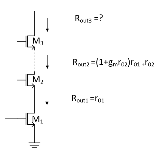
Output Impedance Of a Triple cascode
Should Rout3 > Rout2 ? at DC and at higher frequencies, for example 50GHz
Thanks in advance
Yes.
Series connection of capacitances.
So |Zout3| > |Zout2|.
I want to know about the real(Zout3).
Even a simple model of "real Zout" at 50 GHz has to consider at least all transistor capacitances.
Zout3=Rout3*1/(j*omega*Cout3)/(Rout3+1/(j*Cout3)).
real(Zout3) is not equal to Rout3.
That?s all.
Can you surely understand Rout2 ?
Cout1 is not small by gm in Cout2.
Can you understand following ?
https://www.edaboard.com/showthread.php?385709#7
The problem I have is that when I have just a cascode connection, the circuit is stable but when I connect 3 or 4 transistors in the stack it is not stable anymore. The reason I see is the real part of output impedance of the stack is negative.
Yeah now I see. In gain formula gm*r0 (at DC), the r0 is Rout3 and not real(Zout3).
Yes, you can see it, if you calculate the impedance with sufficient complex model.
Negative real part is due to Y12.
You don?t care about feedback path of each MOSFET at all.
Surely learn very basic things before EDA Tool Play which you like.