why PLL loop flilter always in low frequency (10to 100KHz)?
I had a questions, the PLL will help to filter out the output phase noise at frequency winthin PLL the low pass filter. Then why not design a PLL with high loop bandwith of low pass filter? As I know, the low pass filter bandwidth is normally 10 to 100 KHz. Why choosing such a low bandwidth? Why not use a bandwidth of 10MHz or even more to help the output phase noise?
Thanks
You are right if there is the VCO noise only.
The other noise is phase detector noise, low pass filter noise, charge pump noise and frequency divider noise.
Which one determined the low pass frequency (10 to 100Kz), phase detector? Could you please explain more?
Thanks
You can't discuss the question without specifying some PLL parameters and the specific function of the PLL. Most synthesizer PLLs e.g have a low reference frequency to achieve a reasonable frequency resolution. They obviously need a low loop bandwidth according to stability requirements. Others have the purpose to filter reference frequency phase jitter.
liletian, you shouldn`t think of noise only.
Besides filtering (noise, spurious components) the loop filter determines the dynamic properties of the closed loop (flywheel behaviour).
And - as FvM has mentioned - these properties depend on the specific function of the PLL.
And you should consider phase noise of the PLL.
You original statement, that PLLs ALWAYS have low corner frequencies is wrong. I have done standard loops with up to 1.5 MHz bandwidth, and an injection locked loop is typically tens of MHz wide locking bandwidth.
If you do a careful noise analysis, you will find that for a microwave PLL that uses a low frequency crystal oscillator (below 50 MHz), then the optimum phase noise requires the control loop open loop bandwidth be somewhere in the 3KHz to 250 KHz range. Finer step sizes typically required smaller control loop bandwidths for both noise and spurious reasons.
But if you were locking a wideband microwave VCO to, perhaps a 633 MHz saw oscillator, and tuning in a 633 MHz step size, you would probably get optimum phase noise with a loop bandwidth somewhere in the 1 to 2 Mhz range.
Higher bandwidth loops require special techniques to keep some phase margin.
A simplified analysis shows the reason. Assume a PLL with a divide by 1000 on the VCO and a divide by 1 on the crystal oscillator. Ignore noise sources other than the free running VCO and the Xtal oscillators (for clarity/simplicity in this example).
20 Log 1000 = 60 dB
Here is a curve where the free running phase noise of the VCO is plotted. I also plotted the phase noise +60 dB of the crystal oscillator.
Then I plotted two resulting phase noise curves, one in red if the control loop bandwidth is around 30 KHz, and the other in green if the control loop bandwidth was around 1 MHz. Which PLL output would you rather have?
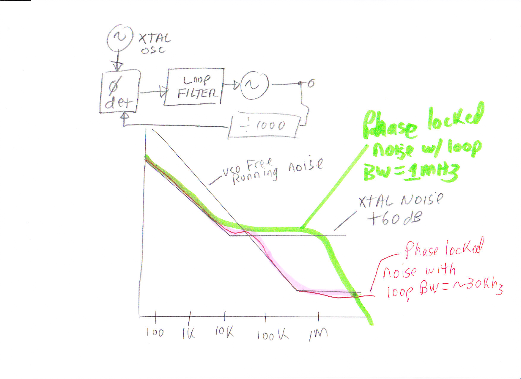
In real life, engineers carefully measure VCO free running phase noise and crystal reference phase noise, along with other noise sources (phase detector, amplfiers, etc) and chose a control loop bandwidth that makes the best of a bad situation (too much noise at microwave frequencies).
Rich
You can run ADISimPLL free software of Analog Device to get the simulated phase noise of your VCO system.