Loop Antenna Practical Considerations
时间:04-04
整理:3721RD
点击:
Hello,
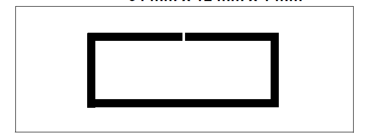
I am trying to design a small device to operate on 868/915MHz band. Since size and cost are top priorities we decided to design the PCB as small as possible and also embed a small circular loop antenna on the device. Now, one of the problems of the loop antenna is the high-Q behavior it exhibits. Keeping that in mind, we decided to do two different designs:
1) ordinary small loop antenna
2) Double loop antenna with magnetic coupling
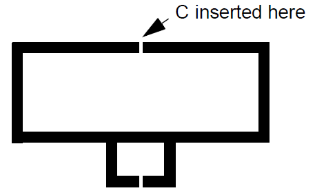
When it comes to achieve resonance, both antennas require approximately the same series capacitor. However, to perform impedance matching antenna 1) requires a impedance transformation network (parallel capacitor), while 2) achieves that via magnetic coupling. I simulated both structures on HFSS and fabricated both on standard FR4. Antenna 2) is already working after some fine tuning on the resonance's capacitor. However, antenna 1) seems quite impossible to put into resonance, which is kind of odd to me, given that I have more degrees of freedom (can tune resonance and impedance transformation after production). With this in mind I got back to the simulation environment and added some more elements (transmission lines feeding, capacitors pads and so on), which led me to the conclusion that antenna 1) resonance is highly dependent on the load that the source is imposing to it, while 2) suffers almost negligibly from it (I think due to the high transformation ratio between primary and secondary).
The first prototypes only have the feed on the middle, but we want to put some electronics inside the loop, as well as a coin cell on the bottom side of the PCB. Both antenna are placed on a circular PCB with D = 27mm and operate on 868MHz. Does any one have thoughts on this? It seems that antenna 2) may be more feasible for mass production that antenna 1), or am I missing something here? Also, if anyone has a better recommendation for a different antenna for this space constraint I would be gladly to ear.
Thank you for your time.
Best regards
I am trying to design a small device to operate on 868/915MHz band. Since size and cost are top priorities we decided to design the PCB as small as possible and also embed a small circular loop antenna on the device. Now, one of the problems of the loop antenna is the high-Q behavior it exhibits. Keeping that in mind, we decided to do two different designs:
1) ordinary small loop antenna

2) Double loop antenna with magnetic coupling

When it comes to achieve resonance, both antennas require approximately the same series capacitor. However, to perform impedance matching antenna 1) requires a impedance transformation network (parallel capacitor), while 2) achieves that via magnetic coupling. I simulated both structures on HFSS and fabricated both on standard FR4. Antenna 2) is already working after some fine tuning on the resonance's capacitor. However, antenna 1) seems quite impossible to put into resonance, which is kind of odd to me, given that I have more degrees of freedom (can tune resonance and impedance transformation after production). With this in mind I got back to the simulation environment and added some more elements (transmission lines feeding, capacitors pads and so on), which led me to the conclusion that antenna 1) resonance is highly dependent on the load that the source is imposing to it, while 2) suffers almost negligibly from it (I think due to the high transformation ratio between primary and secondary).
The first prototypes only have the feed on the middle, but we want to put some electronics inside the loop, as well as a coin cell on the bottom side of the PCB. Both antenna are placed on a circular PCB with D = 27mm and operate on 868MHz. Does any one have thoughts on this? It seems that antenna 2) may be more feasible for mass production that antenna 1), or am I missing something here? Also, if anyone has a better recommendation for a different antenna for this space constraint I would be gladly to ear.
Thank you for your time.
Best regards
