Laplace Force- Resonant Circuit - Flying Saucer
时间:04-07
整理:3721RD
点击:
For some time I have had the following thoughts in the back of my mind.
Tell me if there is any reality to this idea.
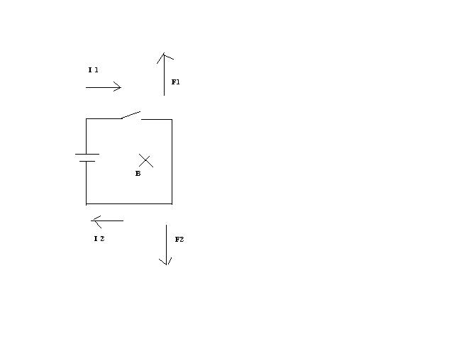
The Laplace force describes the force on a current carrying conductor
when placed in the viscinity of a magnetic field.
F= BiLSin(theta)
F is the force, B is the earths magnetic field, i is the current, L is
the length of the top or bottom half of the circuit and theta is the
angle formed between the current and magnetic field vectors.
Referring to the circuit below, if the switch is closed then the top
half of the circuit experiences and upward force likewise the bottom
half experiences a downward force. The forces cancel.
Lets assume the switch is closed then opened really fast. If the
current experiences a propagation delay when traversing the circuit
then surely when I close and open the switch I create a wave of
electrons. At one point the wave of electron flow in teh top half of
the circuit would exceed the bottom half then likewise the bottom half
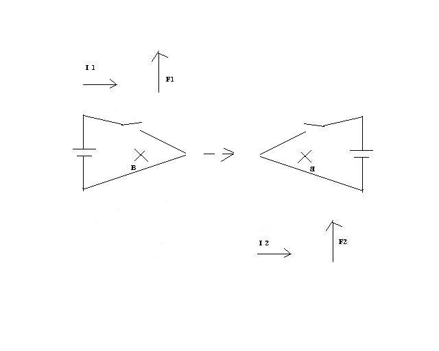
circuit electron flow would exceed the top half. If we could rotate the
circuit about the axis of the battery with such timing that the wave of
electrons in the top half of the circuit contribute to an upward force
and then the wave of electrons in the bottom half of the circuit now on
the other side of the vertical axis would also contribute to an upward
force.
Remove the outer vertical edge of the circuit as it contributes nothing
useful. Rotate the circuit fast enough and strangley it looks like a
flying saucer.
Replace the battery and switch with a High Q resonant capacitor and
inductor. Use electro magnets to rotate the saucer within the earths
magnetic field. Use the vertical axis flow of current and the earths
magnetic field to direct this thing left and right.
Tell me if there is any reality to this idea.
The Laplace force describes the force on a current carrying conductor
when placed in the viscinity of a magnetic field.
F= BiLSin(theta)
F is the force, B is the earths magnetic field, i is the current, L is
the length of the top or bottom half of the circuit and theta is the
angle formed between the current and magnetic field vectors.
Referring to the circuit below, if the switch is closed then the top
half of the circuit experiences and upward force likewise the bottom
half experiences a downward force. The forces cancel.
Lets assume the switch is closed then opened really fast. If the
current experiences a propagation delay when traversing the circuit
then surely when I close and open the switch I create a wave of
electrons. At one point the wave of electron flow in teh top half of
the circuit would exceed the bottom half then likewise the bottom half
circuit electron flow would exceed the top half. If we could rotate the
circuit about the axis of the battery with such timing that the wave of
electrons in the top half of the circuit contribute to an upward force
and then the wave of electrons in the bottom half of the circuit now on
the other side of the vertical axis would also contribute to an upward
force.
Remove the outer vertical edge of the circuit as it contributes nothing
useful. Rotate the circuit fast enough and strangley it looks like a
flying saucer.
Replace the battery and switch with a High Q resonant capacitor and
inductor. Use electro magnets to rotate the saucer within the earths
magnetic field. Use the vertical axis flow of current and the earths
magnetic field to direct this thing left and right.
- How to "de-resonate" a resonant circuit?
- Bulk current injection -Resonant frequency of ESD protection diode CAN bus
- Resonant frequency sensing sensor
- How to reduce/shift the resonant frequency of patch antenna array?
- Shifted Resonant Frequency between HFSS simulation and PCB antenna
- Re: Shifted Resonant Frequency between HFSS simulation and PCB antenna