How to "de-resonate" a resonant circuit?
Sorry to crash the RF-party with a question that at first glance seems misplaced, but I have the feeling that the answer lies in the mind of an RF-aficionado - (but as usual I could be wrong)
I have this theoretical circuit here below
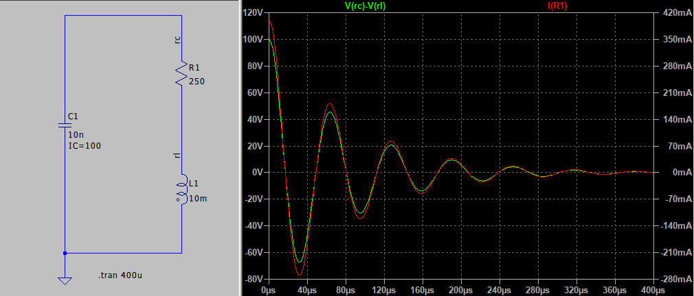
My objective is that the energy stored in the capacitor is dissipated in the resistor in the most simple and efficient manor, without alternating the current.
So either I have to "de-resonate" the circuit and/or level-shift the current so that it does not go through zero.
it is not possible to change the given components, but you can add components to the circuit as you like.
What are my options? Do such techniques exist?
you can put an RC snubber across the L, for critical damping Rd = SQRT (L/C ) for more damping => bigger C ( and correspondingly smaller R )
or, you can put an R across the L.
Thank you, that certainly works - but would it be possible to use some kind of choke e.g. ferrite beads?
short answer = no, not for that size of ringing - ferrite beads have to have lossy ferrite in order to provide damping - just make the original choke out of iron laminations - or solid soft iron for a core - that would be lossy enough ...
Clamp the inductor with a diode.
Replace the resistor with a current source.
Choose an inductor that saturates at low currents to limit resonant energy storage.
Though you?re not clear on the scenario. Is this a circuit you control or parasitics you don?t?
I tried the snubber suggested by Easy peasy which worked, and I guess a diode could also do the trick.
The resistor is given and is sort of the load, so I can't do that.
The inductor is given, so I can't do that either.
The scenario is still unclear to me - so that's why I'm equally unclear. I do not control the circuit as such, I could request change the voltage and the capacitance of C1, then R1 would have to be changed but the inductance of L1 would remain largely unchanged. And then the new circuit would still resonate and the problem would remain.
in the meantime I managed to offset the current so it doesn't go through zero (but it still resonates), for the time being that is considered good enough.