Basic question in cadence
时间:04-07
整理:3721RD
点击:
Hello All,
While working for a while in cadence virtuoso, I had some queries. Thought that I will post it here and someone can clarify the same. But these are the basic questions. An expert may feel that these are nursery Qs but help me as I am newbie to this and none are here with me to clarify the same.
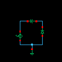
Attached is the circuit diagram, a basic clamp circuit.
Here comes my list:
I have Vsin, Cap from the analoglib library and the diode from UMC library as the model name of the diode was associated with it in the UMC library.
I need to check for the a.c voltage how diode responds and what will be the ouput voltage across the diode.
I have given the parameters as a.c. magnitude is 20V and frequency is 13.5MHz. Selected cap is 1pf.I need to simulate and check the voltages using Spectra.
1. How do you check the voltage across the capacitor/diode?
When I have opened the window for spectra simulation, it prompted to select the a.c/d.c/transient and some other responses.
When I opened another tab to select the outputs, it has prompted whetehr you select the ouputs from schematics. So, I selected that option. Then the window has automatically, taken me to schematics page. and here comes my doubt. When I tried to measure vol across any device, it didn"t allow me to select in that manner. It has opted me to select either the node (plus or minus) or the net. If I want to measure vol across diode, it has posed me to select either D2 plus or D2 minus or the net Gnd. I am confused here. How will I measure the vol across the diode for the specified input.
Please help me.
While working for a while in cadence virtuoso, I had some queries. Thought that I will post it here and someone can clarify the same. But these are the basic questions. An expert may feel that these are nursery Qs but help me as I am newbie to this and none are here with me to clarify the same.
Attached is the circuit diagram, a basic clamp circuit.
Here comes my list:
I have Vsin, Cap from the analoglib library and the diode from UMC library as the model name of the diode was associated with it in the UMC library.
I need to check for the a.c voltage how diode responds and what will be the ouput voltage across the diode.
I have given the parameters as a.c. magnitude is 20V and frequency is 13.5MHz. Selected cap is 1pf.I need to simulate and check the voltages using Spectra.
1. How do you check the voltage across the capacitor/diode?
When I have opened the window for spectra simulation, it prompted to select the a.c/d.c/transient and some other responses.
When I opened another tab to select the outputs, it has prompted whetehr you select the ouputs from schematics. So, I selected that option. Then the window has automatically, taken me to schematics page. and here comes my doubt. When I tried to measure vol across any device, it didn"t allow me to select in that manner. It has opted me to select either the node (plus or minus) or the net. If I want to measure vol across diode, it has posed me to select either D2 plus or D2 minus or the net Gnd. I am confused here. How will I measure the vol across the diode for the specified input.
Please help me.
Choose analysis (transient i suppose is the one you want) and after simulation has finished from the top menu of ADE L plot the transient signal on the net you want.
If you want to observe the voltage across the capacitor then from the top menu of ADE L again go to Direct Plot-->Main form,choose differential nets and hit on the nets of each side of the capacitor.
Thanks jimito13 for the help. I understood, experimented and experienced the results. Thanks a lot!