onchip Balun design between LNA & Mixer
i want to design a balun using ASITIC software that will take single ended i/p from LNA & give differential output to the mixer stage.
the main problem is the equivalent model of balun & the parasitic extraction analysis of balun in asitic?
i want the balun to work in 2.4 GHz range for ZIGBEE SYSTEMS.
Hi,
I have used ASITIC for several applications and find it gives accurate results for simple on-chip inductors, accurate in terms of both inductance and Q. More complex structures, such as tapped inductors, are not so accurate but still give reasonable results. An important aspect to the accuracy of the simulation is the data provided for the various layers. These values should be in the process documentation.
To make a single ended to differential output balun requires one input to be grounded. Also, the inductor will consume quite a large area of real estate. You might want to consider other ways to connect the LNA to Mixer. One way is just connect one mixer input to ac ground. There will be a linearity penalty but perhaps that is OK for your system
Design your balun in ASITIC and then optimize in Momentum of ADS or Sonnet..
hi BigBoss,
sorry i saw ur comment very late...
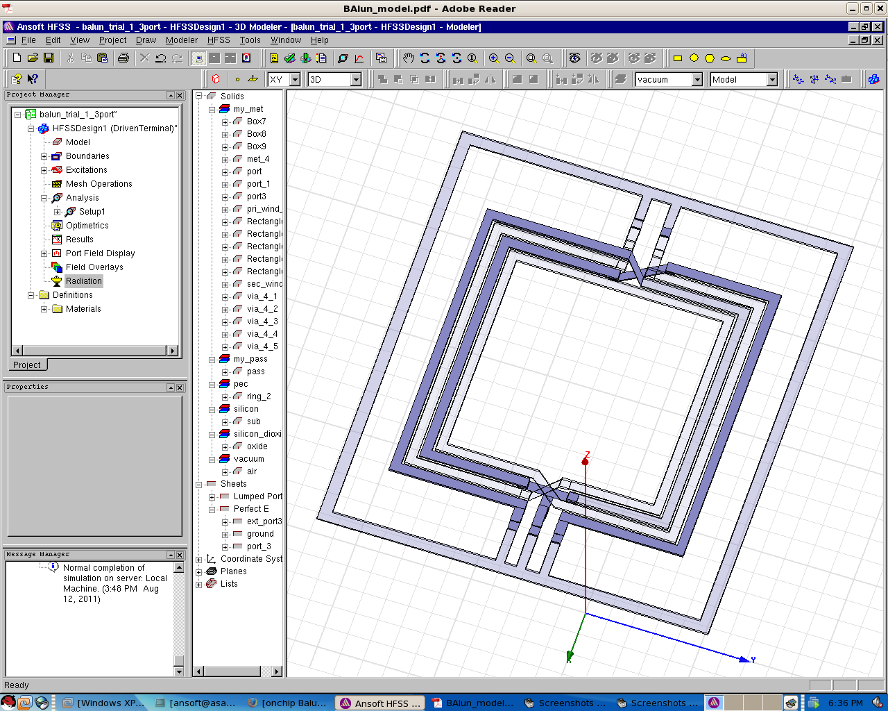
i dont have sonnet or momentum but i have HFSS (3D EM solver)
is it possible to simulate a balun in hfss ?
i have made the centre tapped structure & you can see in the image attached below........
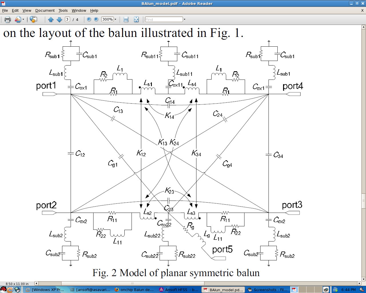
now i dont how to extract the parasitic parameters like Ls, Rs, coupling coefficient between 2 coils. I have attached the equivalent ckt diagram that i am simulating in cadence i.e. its
model