Help on PIN Diode use as a switch for reconfigurable antennas
时间:04-07
整理:3721RD
点击:
Hello All,
This is my first post on this website. I am an undergraduate EE student entering my 5th and final year and I have an antenna fabrication question....
I want to fabricate a reconfigurable microstrip patch antenna which will employ PIN Diode switches to change the geometric shape of the patch to acquire different frequencies, hence reconfigurable.
My question is how to utilize the switch? I know I will need the pin diode itself, inductors to be used as RF Chokes (prevent RF signal going into the DC bias lines), capacitors to block DC voltage from entering the antenna or RF signal, and the DC Bias lines themselves to feed the diode power to switch from the Closed (ON) state and Open (OFF) state. But how do I specifically configure this circuit? Series or parallel combination? The size of all parts will be 02-04's (1mmx0.5mm) and the space between the altering patches will be 2mmx2mm.
-Thanks a bunch everyone
I would look for 0402 dioedes and cap, but long 1206 size inductor.
Rich
This is my first post on this website. I am an undergraduate EE student entering my 5th and final year and I have an antenna fabrication question....
I want to fabricate a reconfigurable microstrip patch antenna which will employ PIN Diode switches to change the geometric shape of the patch to acquire different frequencies, hence reconfigurable.
My question is how to utilize the switch? I know I will need the pin diode itself, inductors to be used as RF Chokes (prevent RF signal going into the DC bias lines), capacitors to block DC voltage from entering the antenna or RF signal, and the DC Bias lines themselves to feed the diode power to switch from the Closed (ON) state and Open (OFF) state. But how do I specifically configure this circuit? Series or parallel combination? The size of all parts will be 02-04's (1mmx0.5mm) and the space between the altering patches will be 2mmx2mm.
-Thanks a bunch everyone
Thanks a lot guys.
I would be tempted to try something like this. A DC voltage on the feedpoint will turn on the PIN diodes if positive, and turn off the PIN diodes if negative or zero. By playing with the shapes you can probably get a dual band response as a function of pin diode biasing.
I would keep the structure symmetrical!
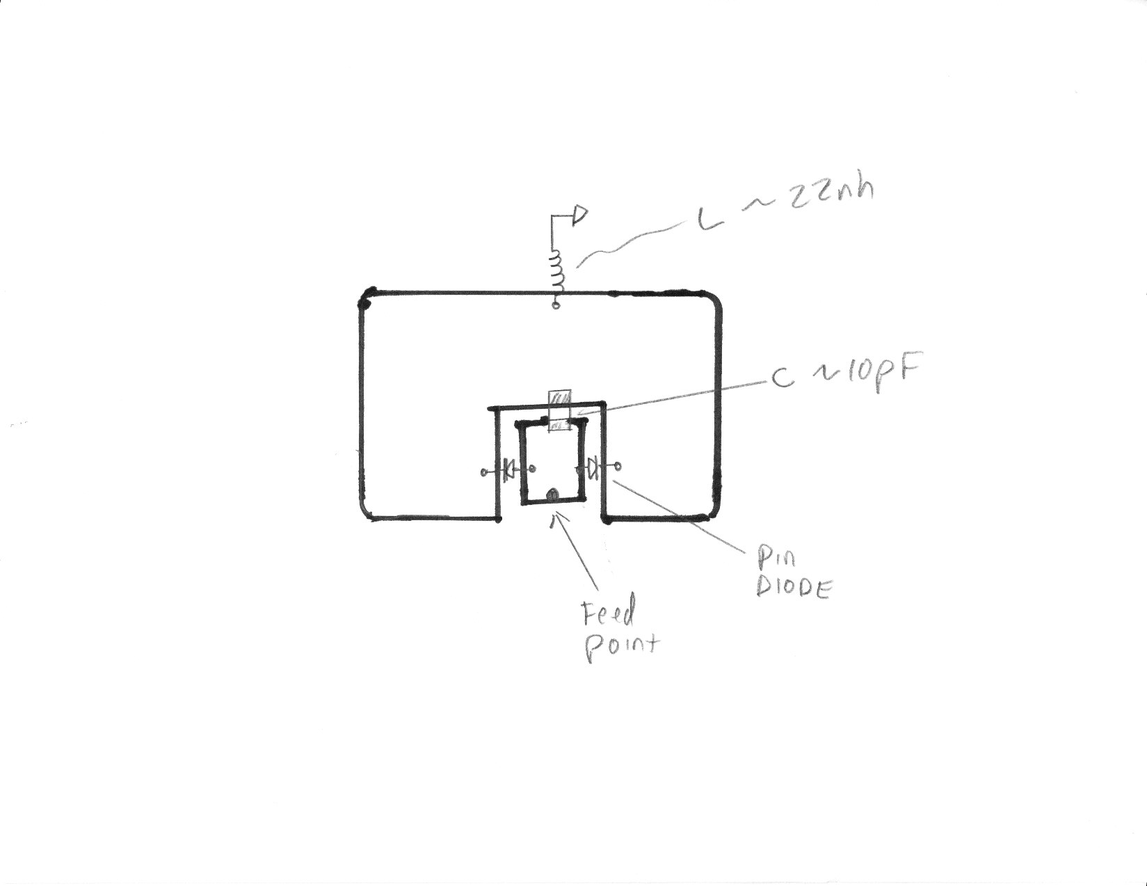
I would look for 0402 dioedes and cap, but long 1206 size inductor.
Rich
Thank you very much.
for simulating diod you can only use a little rectangle strip. by inserting the strip diod is ON and by removing this strip diod is off.