Signal Amplifier using PD A1GHz: board design
I trying to build an amplifier that do the next:
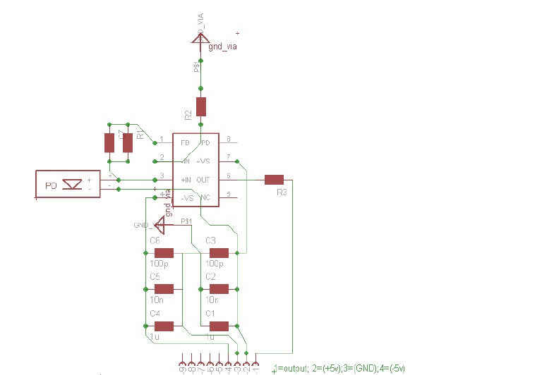
PD is connected to an opamp (AD8000) which his output is the desired RF signal.
The requirements is wide band-pass and at least 1GHz.
because the high freq' I assume that I will need to match the impedance (50 Ohm) using microstrip between the PD and the +input of the AD8000 and between the AD8000 output to the BNC connector.
I could use any theoretical literature (on-line books, websites etc.) and practical advises regarding: microstrip, PCB design, PD for fiber,ways to reduce noise from the power-supply, impedance (matching) etc.
It is crucial for me since it is the first time I am doing such thing and I will have access only once to the CNC to produce the PCB.
The schmatic design I have in mind is attached.
I dont know yet the feedback capacitor/resustor becuse I cant find a way to calculate the proper values for them.
any help will be welcomed,
Tzahi
Hi,
i think could be better to use any Minicircuits' MAR series amplifier or any other gain block.
It depends primarily on your final application... what is the gain you need, the bandwidth, the noise figure.
Most of these MMIC (built by MACOM, HP/Agilent, Avago, Stanford, Minicircuits...and many other) have both input and output
matched to 50 ohms (while AD8000 doesn't), gains up to 20dB to 1GHz and beyond (AD8000 has a bandwidth
of "almost" 1GHz with gain = 1).
There are MMICs optimized for "power" applications (up to 20dBm output like Minicircuits' ERA 5) and small-signal amplification
(noise figures as low as 1dB like the very good MGA 62563)...as i wrote, the choice depends on your application.
Notably, many of them are also unconditonally stable...and it is a very desirable feature!
Usually they have 4 pins, where two of them are the ground connections, one is the input and another is the output.
You then just have to put 2 decoupling capacitors, one for the input and one for the output, then calculate the
biasing resistor for power supply, that's all.
For the input / output strips, you can use a 3 mm width of copper over a 1.6mm height FR4 PCB and it is important
to have ground thruholes near the ground connections of the MMIC and near the DC decoupling capacitors.
I really don't think that you can get anything good (up to 1GHz) out the AD8000.
Bye
Tom