Simulate 13.56M Loop PCB Antenna Use ADS Problem
时间:04-07
整理:3721RD
点击:
Recently I use ADS Simulate Loop- PCB antenna, and it?s frequency is 13.56Mhz. Acturally I use Vect Network Analyser to measure this antenna?s inductor value is 1.6uH, but now when I simulate it in ADS, it is very different with acturally result.
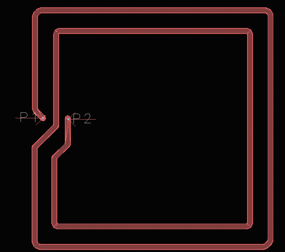
PCB Antenna Picture
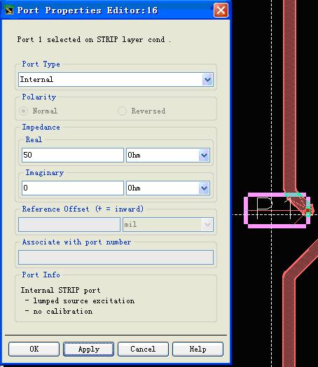
Port1 Setting
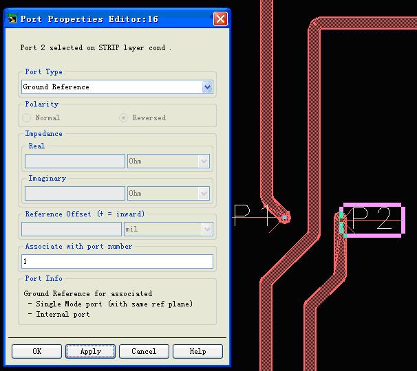
Port2 Setting
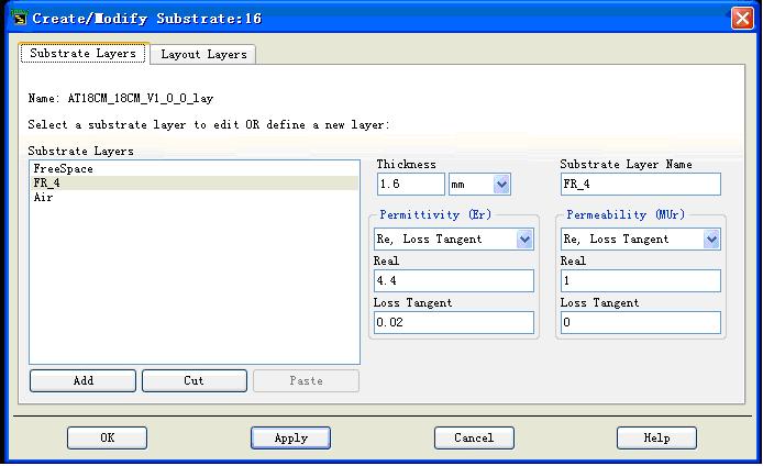
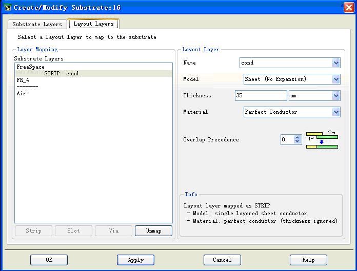
Substrate setting
Layout Layers Setting
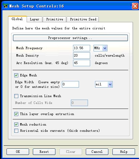
Mesh Setting
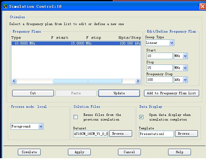
Simulation Setting
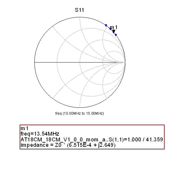
Simulation result
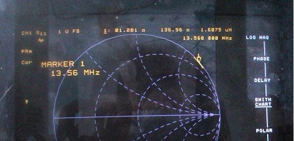
Actual measure result S11 of the pcb antenna
From the simulation result, we know this impedence is 50*(4.02E-8 + 0.068j), it?s equivalent circuit is a resistor series a inductor, the resistor?s value is 50×4.02E-8, and the inductive reactance is 50×0.068 = 3.4 = jwL = 2*3.14*13.56 E6 => L= 0.0399uH, but I use Vect Network Analyser to measure this antenna?s inductor value is 1.6uH, so why ?
This is my Project , Can somebody help me?
13M56_Ant_prj.rar
PCB Antenna Picture
Port1 Setting
Port2 Setting
Substrate setting
Layout Layers Setting
Mesh Setting
Simulation Setting
Simulation result
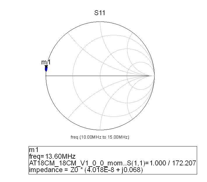
Actual measure result S11 of the pcb antenna
From the simulation result, we know this impedence is 50*(4.02E-8 + 0.068j), it?s equivalent circuit is a resistor series a inductor, the resistor?s value is 50×4.02E-8, and the inductive reactance is 50×0.068 = 3.4 = jwL = 2*3.14*13.56 E6 => L= 0.0399uH, but I use Vect Network Analyser to measure this antenna?s inductor value is 1.6uH, so why ?
This is my Project , Can somebody help me?
13M56_Ant_prj.rar
RFID coil is effectively a pure AC magnetic problem that don't need a full featured EM solver. Nevertheless should it give correct results. I read about a cellsize setting of 20 cells/wavelength, which refers to a cell size of about 1.1 m. Don't know if this is a problem.
Hello everybody!
This problem is solved, the real size of the antenna is 180mm * 180mm, but the layout is 180mil * 180mil, so it is wrong. When I change the scale , the simulate result is very close to the true result. Select the layout then chose edit-》 scale.
Nice fault. Would be interesting, if you get realistic resistive impedance part as well when putting in copper conductivity.