What is the "integration line"? (HFSS results included, WR-90 from HFSS tutorial)
Before getting down to business, I beg your pardon for my poor English.
I have been studying "Microwave engineering by Pozar" by myself (self-independent study).
Please regard me as a newbie.(But I have a mathematical background required for studying this book)
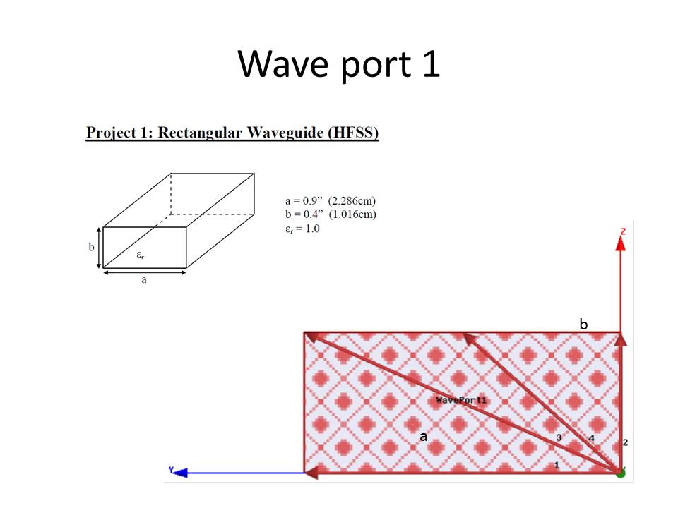
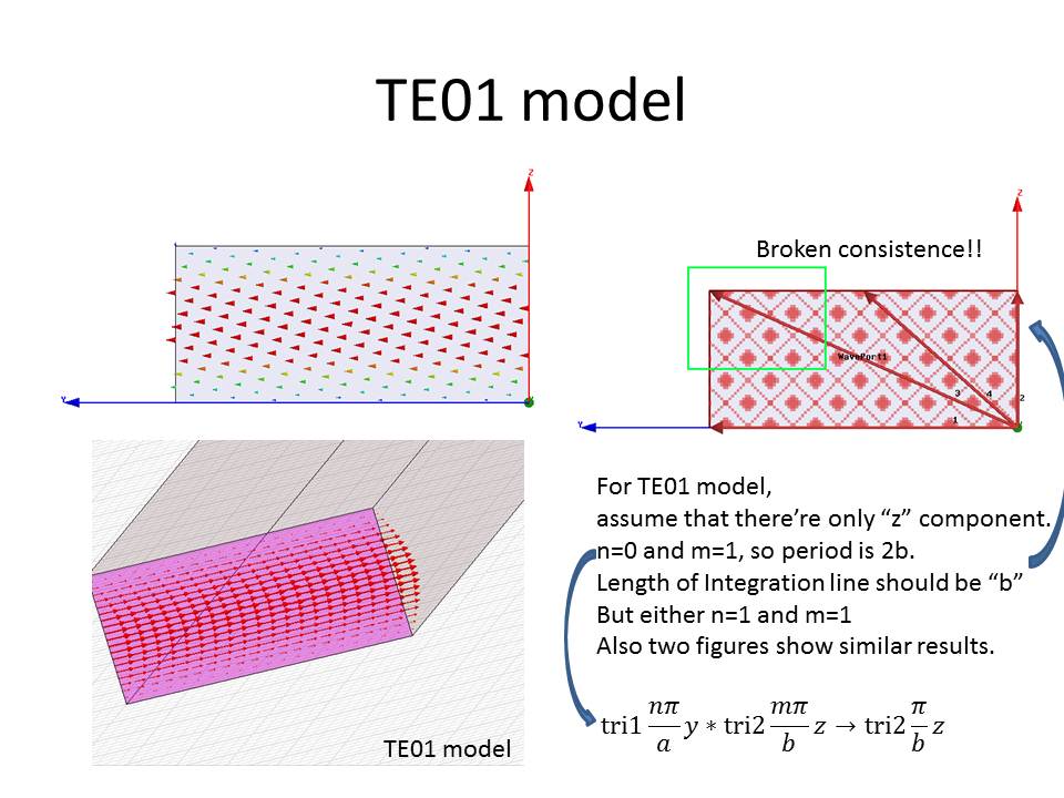
So, what is the "integration line" exactly? I have been studying the "rectangular waveguide" and to visualize the EM fields, I did HFSS simulation following WR-90 tutorial from Ansoft.
but there's no exact information about integration line except "Draw the integration line as you wish"
I attached my HFSS results with those from tutorial to be compared
Regards.

Integration line is related to modes.
For more details refer to the attachment.
The integration line defines the mode to be solved by the solver.
Hope this help you.
Thanks, but actually, what I consulted was that book.
There's no exact information about integration line in that tutorial.
The integration line is used to extract the impedance for a given waveguide cross section. There are three methods to extract the impedance in HFSS: Zpi, Zpv, Zvi. The Zpi (default) uses the initial power, 1Watt, and the enclosed current, I, to determine the impedance. The enclosed current is determined by the line integral of H around the periphery of the wave port (as it is a PEC boundary) so no integration line is required. The Zpv uses the integration line that is defined to integrate E upon, and it is best to define this line in the path of expected highest potential. As the line integral of E is the voltage, Zpv uses the initial power, 1Watt, and the voltage, as determined from the integration of E along the path defined by the integration line. Zvi determines Z using the voltage and the enclosed current.
The integration line also serves to set the initial phase (polarization) of the modes.
IMO, it is best simply to use the Zpi representation and not assigning integration lines in nearly 99% of waveports.
Have Fun
results HFSS integration 相关文章:
- diffrent results in hfss feko and cst
- Simulation in ANSYS of a paper do not get the same results?
- Wierd S-Parameter results simulating C-Band PCB traces in CST Studio.
- Lumped and Distributed Circuits results error
- Different Results in Transient Simulation with S-parameters from file in ADS
- Help with results of a Wirelles Power Transfer Circuit.