Best software for analysis of Yagi-Uda and Coaxial Colinear antennas
http://www.engr.colostate.edu/~notar...20Antennas.pdf
Build A 9dB, 70cm Collinear Antenna
joined end-to-end, with the outer of one connected ot the inner of the next.
I know Yagi-Uda antennas can be analysed by the method of moments with things like NEC, but I've had less than ideal success with that. Simulations and measured data have not agreed as well as I would have expected. I've used MMANA-GAL, but my boom is quite large (25 mm diameter) and the elements 12 mm diameter placed just above the boom with an electrical connection between them. I guess this means the bottom of the element sits about 10 mm above the boom. Clearly the boom has a major effect at high frequencies (I'm intersted in up to about 500 MHz).
I'm also stuck with a folded dipole with a bend radius of 35 mm. I've tried approximating the radius with line segments, but that presents issues since to get an accurate fit to a curve one needs a lot of segments, by which time their length is comparable (or even smaller) than their diameter. I think the MoM breaks down under these conditions.
I don't know how to be model the CoCo antenna, though I have wondered if a FDTD method would work. Certainly the NEC code can't, but I'm not sure if more advanced MoM software can. The issue is there are two dielelectrics - air and the dielectric in the coax.
There are other antennas I want to model too, but most are electrically quite large. I'm less interested in patch antennas.
I believe Microwave Office, FEKO and HFSS are all possibilities. Does anyone know how these might compare on these sorts of antennas?
Dave
Microwave Office has EM solvers that are specialized for planar work, so this is not an option for your 3D antennas.
What do you think are likely to my best choices? CST Microwave Studio, HFSS and FEKO seem to me like strong possibilites, but am I mistaken? Are there any more I should be looking at?
Would the FDTD method be suitable for the Coaxial Colinear (CoCo) antennas? I did give some thought to actually writing a FDTD program for the CoCo antenna, but whilst I understand the basics of Yee's algorithm, I don't know about any of the subtleties which I believe would be crucial to actually making something work well.
I have some difficulty in believing the CoCo antennas work the way claimed. If you believed the theories like the transmission like sections have to be a half-wave electrically, then one could shrink them to under 1 mm long for UHF work if one used a dielectric with a very high permittivity (100,000+ does exist). I'm suspicous of the whole concept of that antenna.
Dave
Dave
Yes, I just gave it a quick try with my FDTD simulator (Empire XCcell).
Agreed. Don"t re-invent the wheel. Here is an FDTD tool that is free for personal use: emGine Environment - 3D Electromagnetic Field Simulator in Time-Domain for Design, Analysis, Optimization of RF and Microwave Circuits, Filters, Antennas, Resonators, Hollow Waveguides; Free for Non-Commercial Purposes with Open-Source GUI; Windows,L
I see your point and would agree. At least there is a discrepancy between the resonance condition in the coax itself and the resonance of the radiating element (coax shield in air) ...
Thank you. That sure has a good S11 - shame the radiation pattern is not as impressive. I'll have to take a look at your software, as I was not aware of that product.
I do want the software for commerical use, but given emGene is free for non-commerical use and one can get a 6-month trial for commerical use for no charge, it seems likely it is not expensive to buy a commerical license. I can't imagine it the sort of price of FEKO, HFSS or similar.
I tried emGene without success on my 64-bit Windows Ultimate machine. Windows detected it had not installed properly, and gave me the option of accepting it was installed OK, or reinstalling wtih the reccomended settings. First I indicated the install was OK, then tried reinstalling, but neither worked. I can't fully uninstall it (something remains on Windows menu), but can't get it working by reinstalling either. So basically emGene is non-functional for me.
I'm glad I'm not the only one to find this a bit hard to believe.
A friend, who like myself is a radio ham, built one for 2 m or 70 cm (I'm not sure which) and did not find it worked well. However, his tests were based on just how strong local signals were and were not conducted under laboratory conditions. He found it was worst than a quarter wave whip. But I've got no idea how good the design was he started from - a lot of designs in the amateur press are poor.
I'm trying to get my head around this CoCo antenna, and to deteremine if it does work, and if so how to optimise it. I think it is potentially intersting, but there seems to be a lot written about it, that's just not substantiated. Like that link I provided. It is said to provide 6 dB gain (no reference specified), but it's not specified how that figure is arrived at.
Dave
Dave, that agrees with my simulation results (~ 5 ... 6 dBi)
I made an error - the author of the article "Build A 9 dB, 70cm, Collinear Antenna From Coax By N1HFX"
Build A 9dB, 70cm Collinear Antenna
claims 9 dB gain, not 6 dB as I stated. So it does look like his figures are exagerated somewhat. Note however he has 8 half-wave sections - I'm not sure how many you are using.
I've seen people claim to double the gain as you double the number of sections, but that seems unlikly to me. As the lower sections radiate, there is less current in the upper sections, so it seems they must contribute less towards the far-field.
I'd be interested to play with your software and see what I can do with this antenna. I've submitted an evaluation request.
An obvious thing to try is to increase the permittivity to make the sections short (or I guess easier, just work at a lower frequency), and to decrease it to 1.0, to see if it works better if air-spaced. It's possible a foam dielectric cable, with a high velocity factor, might give better performance than RG213. (I've got some "air-spaced" coax at home. It is rated for very high power, and basically consists of very little dielectric supporting the inner conductor. It is quite expensive - I got a sample for a 5 kW linear I was building, but have never finished!)
How would your software handle Yagi-Uda arrays on boom which are quite large? I'm guessing the FDTD method will use a lot more RAM/time than finite element based programs on such systems due to the fact a finite element system can put a finer mesh where it is needed, where (as far as I know), the FDTD method uses a fixed size mesh.
Dave G8WRB
Hi Dave,
to avoid misunderstanding - it is not "my" software, it is a commercial EM software made by IMST GmbH.
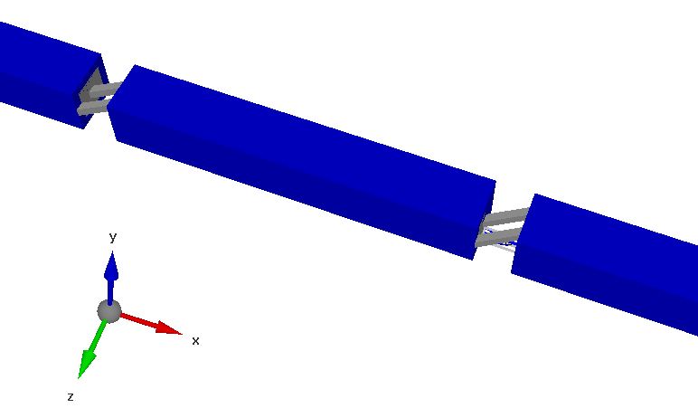
My model had a total of 6 segments, filled with erel=2.2
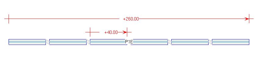
You can see the dimensions in the screenshot. The lambda/4 resonance for these segments is at ~1.3GHz.
In general, I would not use FDTD or FEM for "wire" antennas. Your case seemed interesting, so I gave it a quick try, but this is not what the software was designed for. Also, it is way to expensive for ham radio applications....
It's not that simple. FEM needs less mesh cells for geometry approximation, but FDTD memory requirement scales much nicer (linear) with the number of mesh cells, so that models with >100MCells are no problem.
For my model above, I used a square coax, to keep the mesh simple. The simulation time was a minute or so, without tuning for simulation speed.
Hi,
I'm sorry, for some reason I thought you were the author.
Sorry, I missed that top diagram. It was very thin and faint on my screen. I see the others, but not that one. Hence I did not know how many elements you used - I assumed 8.
Although I gave a link to a ham site, and I'm a ham, I do want this for the design of antennas professionally.
Looking at that top diagram, do you feed this in the centre? I know people have centre-fed antennas with sections of coax like that, but my interest is in feeding at the bottom for a colinear.
A minute seems pretty good. I could easily try different ideas out with that sort of simulation time.
If your model with 6 sections gives 6 dBi gain, I somewhat doubt adding a couple of sections to make 8 (the same as that article) would give the 9 dB gain he quotes, though of course I don't know if he means dBd or dBi.
BTW, would you mind emailing me the file you used for the simulation. Then if I get a trial copy, I can probably get somewhere faster. You should be able to mail me directly from this site.
Dave
Hi Dave, this was with center feed. The model file is attached.
Thank you. If I get a trial of that package, it will give me something to work with.
This idea of crossing the braid and inner conductor got me thinking about crossing over the wires of balanced feeder, which would be a lot easier to do, as it would only require a twist. I'm going to try to model that with something like MMANA-GAL tomorrow.
I've currently got a trial copy of FEKO, CST, AWR, Sonnet and should have HFSS tomorrow.
I also got a trial of Antenna Magus (full version), but are most unimpressed with that considering it is nearly 8000 Euros. If you design a Yagi-Uda antenna, you can't even select the impedance! What use is that?
Dave
Dave, I would expect that other antenna types are more relevant for professional EDA customers.
The guys who optimize yagis tend to use free software anyway, so there's no business.
Hi Dave,
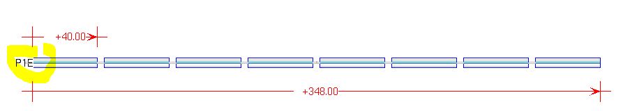
here are the results for 8 segments and feed at one end. Segments are the same as before, 40mm length and erel=2.2.
Volker
Dimensions:
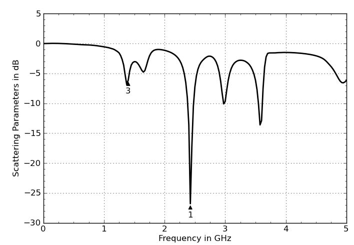
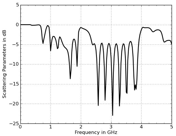
S11:
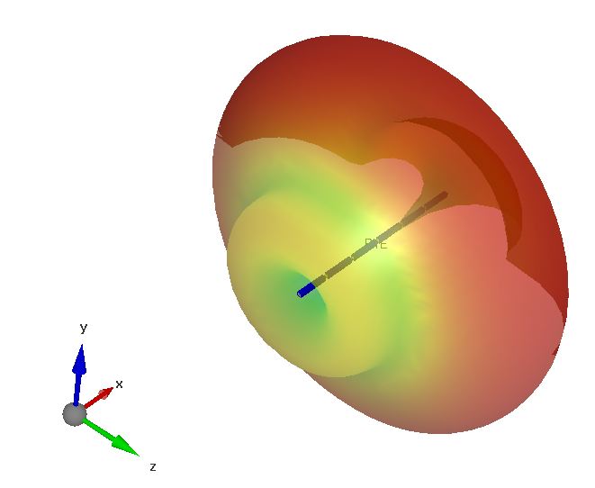
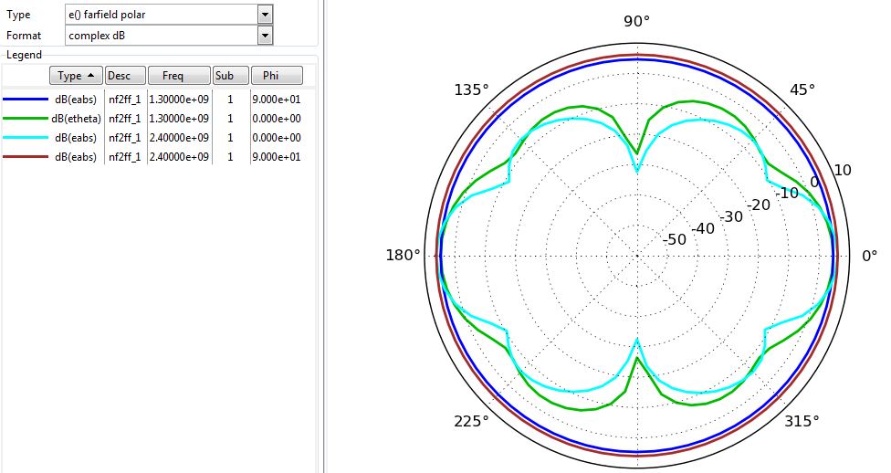
Pattern 1.3GHz and 2.4GHz:
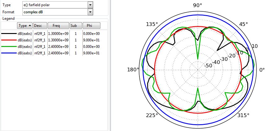
Pattern 1.3GHz
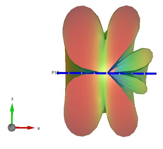
Pattern 2.4GHz
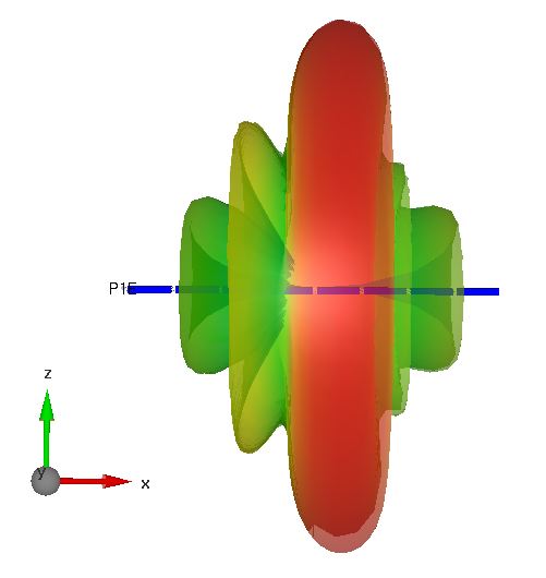
Thank you. Am I interpreting this correctly when I conclude the peak gain is about +7dBi and the radiation peaks at about 10 degrees above the horizon, with around 6 dBi gain in the horizonal plane? I assume it is possible to display the data like gain in a tabular form.
I've got a trial of this software (awaiting license file before I can run it), so I will look at this later in more detail.
Dave
Hi Dave,
yes, that's correct.
Volker