phase difference generation
Can some one please tell me how to test AD8302 evaluation board for phase measurement..
I dont know how to generate two phase different signals...
I have got RF signal generators , spectrum analyzer & a 2 port VNA.
Can you please tell me the simplest way to do the same accurately..
the datasheet describes using two generators SMT03 offsetted at certain frequency and allowing the angle to accumulate..
But i cant understand that procedure

Can somebody please help.
Thanks
What I do in similar situations is that I feed signal through a power-splitter and then connect coaxial wires with different length, causing a timing delay between these. Measure S11 and successive cut one coax until VNA shows difference in length is lambda/2 =>180 degree. Other phases can from that length difference relative easy be found for one frequency. Not so very precise method but good enough in most cases.
Most VNA's can directly measure electrical length, which also can be a help to find right coaxial length.
Yep, a time delay difference is one way. I would carefully pad down the detector's inputs, and the source output (at least 3 dB each) so you do not get standing wave screwing with the phase.
But a better way would be to get two synthesizers, both locked to the same 10 MHz reference. If one of the syntheisizers has a phase offset knob, you just vary the phase that way.
Using Mr. Kafeman's approach, if you have a power splitter and two different delay lines to the two inputs, if you sweep the frequency linearly, you would also be sweeping the phase difference linearly. So you could do a crude linearity test by sweeping frequency and watching the detector output on an oscilloscope.
The cheapest and the most accurate phase shifter used for calibration is a 7474 D-type flip-flop, which provides 90-deg phase shift between its Q outputs.
Now they go very high in frequency, but the only issue is that the input frequency is divided by 2 at the output.
The datasheet method to apply a fixed frequency offset and get a continuously variable phase shift with high linearity seems reasonable in my opinion.
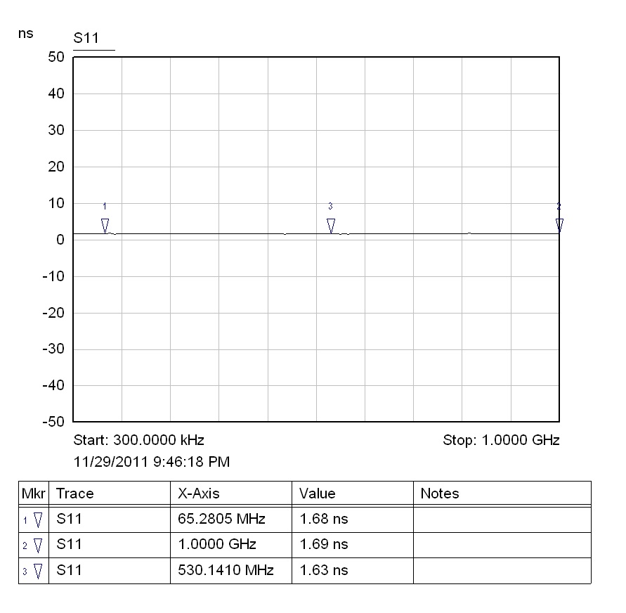
So i calibrated my VNA, connected an N to SMA(female) adapter took a semi rigid coax, connected and soldered its one end to an SMA male connector and connected to the network analyzer.
(I haven't done port extensions, is it necessary?)
I took smith chart and delay readings with some length of coax then i cut the cable to reduce length and took again the same measurements. ( i put smith chart marker to log magnitude format)
1) with a semi rigid cable of fixed length -Smith chart.

corresponding reading in delay format
2)with the same semi rigid cable but length reduced- Smith chart

corresponding delay reading.
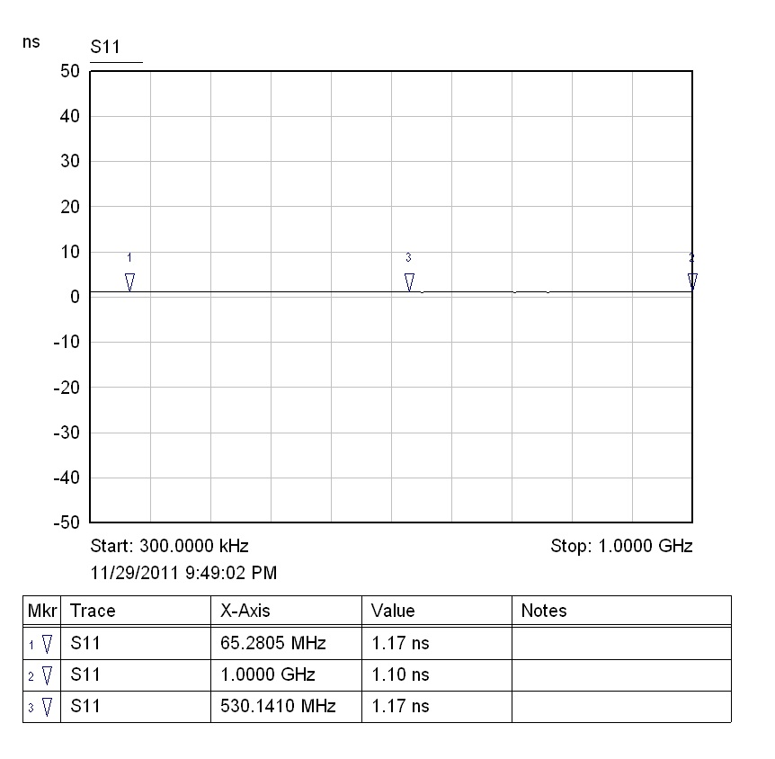
So shall i look at the smith chart or delay format to get the phase difference ..
Im confused can somebody please clarify..
Thanks for any help..
To start with, select a narrow frequency range, type 1GHz - 1.1 GHz, do port extension so you can read 0 degree for a certain length.
Cut 5 mm and compare result. In Smith chart can change of angle be directly read for these 5 mm so you then get an idea what length 90 or 180 degree corresponds to.
Ok Kafeman, thanks for the reply..
I was able to lock one generator to another 10MHz ref out and carry out as biff44 suggested.But i want to try out your method too..
But in biff44 method i gave both input to a two channel oscilloscope through BNC cables.. but may be because of the phase delay in the cables the sinewaves are not starting at the same position.So there also though i could change phase relatively..it think i need to characterize the effect of BNC cable which is used to connect to DUT.