designing the filter at X-band
I tried microstrip structure but that wasn?t satisfactory (The insertion loss was about 2.5 dB in simulation with HFSS and ADS momentum).
Then, I tried Cavity structure but I can?t design the structure for that frequency band (I use Ansoft designer for designing process but the results were too small with disappointing results in HFSS)
Someone suggests me SIW (substrate integrated waveguide) structure. But I have not any idea for designing this structure.
I will appreciate if anyone can help me for Cavity or SIW designing at this band, or any other help.
Thanks in advance.
Wave guide filters gives very low insertion loss.
silver plated waveguide. You might get by with suspended substrate stripline...it would be close.
How can I design the Waveguide filter structure? I saw some simple and standard (made with practical waveguide as wr90) structure; it's simulation results are ok with HFSS but the bandwidth is below 100 MHz (I want 500 MHz). Can I achieve this bandwidth by waveguide structure?
pls send your file to check it
Sure, you can get wider bandwidth if you increase the stages.
Pipe cap filters work very well at 10GHz too :)
http://www.w1ghz.org/new/Pipe-cap_Filters_Revisited.pdf
Dave
A pipe cap filter (single pole) will not do a 500 MHz of bandwidth!
I have attached my primary design here. (my exact desired frequency is 9.2 to 9.6 GHz; rejection in lower side is crucial and not for upper side) as you can see; 1-the dimensions are so large(in length) 2-structure is so sensitive 3-passband frequency is not accurate.
can you help me for amendment and practical advice?
your simulation has too problem is this your last design ?
SIW or Substrate Integrated Waveguide is a planar waveguide structure which is compatible with RF circuitry. It is essentially composed of a substrate with two metal layers and two rows of metallic vias which emulate the side-walls of a rectangular waveguide. the design formulas for SIW are the same as ordinary waveguides, except that an effective width of the waveguide is used. for more information search ieee for SIW articles.
no.can you advice me?
download antenna design kit it help you to design true waveguide
See this figure
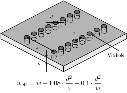
This SIW is equivalent to an ordinary waveguide of width Weff.