negative impedance generation
Is there any method to generate negative impedance at 9-9.6 GHz?
thanks in advance
Hey Dude!
Hi
if you have an opamp in this frequency range , you will can do it as the simple as. But if you don't have it i think gan diode can help you.
Best Regards
Goldsmith
All oscillator circuits working with a two terminal resonator can be considered as negative impedance generators.
Dear FvM
Hi . it is not correct! according to the RF circuit design book, the oscillators are in 2 group: relaxation(with negative impedance) . positive feed back with transistors . when we use a positive feed back to oscillating , we used from bounce (instantaneous voltage change) of power supply and our feed back path that its poles are in the instability region , will keep this situation!
Why you said that?!
Best Regards
Goldsmith
You will need an active device, such as a GUNN or IMPATT diode, FET, bipolar transistor.
In the case of the diode, you simply apply bias a simple impedance matching structure, and they naturally provide a negative resistance.
In the case of a FET or bipolar, transistors manufacturers try to make them as stable as possible so that people can readily make amplifiers out of them that will not oscillate. So you have to employ some sort of feedback to them to make them have a negative resistance on one port.
You will have to load the device S parameters into an analysis program, and then add some feedback elements at various points to try to make the new circuit unstable. Often a small inductance in the source to ground in the FET will do the trick, for instance.
Assume a transistor oscillator connecting to a two-terminal resonator. Then you can describe the oscillator part as a black box. Viewn from the resonator, it must implement a negative impedance (compensating the losses of the resonator), otherwise you won't get oscillations.
That's a more verbose version of my above statement. It doesn't care, how the negative impedance is generated, just states the fact. You can hardly claim it's wrong. The message is, that positive feedback can generate negative impedances in different situations. The original post however didn't specify the intended usage of "negative impedance". Without knowing about it, you can't say which implementation of negative impedance is suitable, and if it serves a reasonable purpose at all.
Dear FvM
Again Hi
I can describe my reason: each bounce has a wide spectrum. and your tank circuit will get your desired harmonic and change its phase as its phase become zero. so amplifier , will amplify it and will get it to the tank circuit and again amplifier will amplify it. when signal be distorted( due to amplification) the tank circuit will reproduce it . ok we will have a good and stabilized shape in out put. when you wanna make a oscillator with negative resistance , we will have this : when you increase the voltage , your current will decrease we can see this effect in gunn diode or impatt diode or in diacs or in triacs or in unijunction transistors or in tunnel diodes. in fact in this devices we will have negative resistance . but in positive feedback oscillators we can not say that we generating negative resistance , we can justify it as you described it but in fact it is not real.
Best Regards
Goldsmith
Goldsmith, just one short comment:
You have not the correct understanding of a negative resistance.
Of course, the current also gets larger after increasing the corresponding voltage - however, the direction of the current is opposite to the "normal" case.
That means: negative current ! But its magnitude still is proportional to the voltage: R-=V/(-I)=-|R|.
I'm simply unable to see a principle difference between those special components with partially negative I/V characteristic slope (e.g. gunn diodes) and circuits with other active components that implement negative impedance by positive feedback.
Dear LvW
Hi
Negative resistance is a property of some electric circuits where an increase in the current entering a port results in a decreased voltage across the same port.
see these sites please: Negative resistance - Wikipedia, the free encyclopedia
Negative Resistance Oscillators
Oscillators - Feedback Oscillators Page 1
Negative Resistance Revived
I think the mean of these sites are the lc circuits with combining to the negative resistance such as tunnel diode or etc can oscillate . but i cant find the transistor oscillator as a negative resistance oscillator ! is it possible explain your mean? why in the transistor oscillators i can not see a negative resistance curve?
Best Regards
Goldsmith
Really? Transistor as negative resistance device for oscillator is well known and widely used.
Again Hello my friends!
Is it possible explain that how the transistor can use for creating negative impedance?
Thanks in advance
Goldsmith
http://www.hp.woodshot.com/hprfhelp/...her/ana008.pdf
Microwave Transistor Oscillator
dear roommates
thanks for your replies
an other question that deal with negative impedance: what's the maximum and minimum value for negative resistance that
that reachable using your suggested methods?
Hi Goldsmith, thanks to referring to wikipedia. Now I know what you mean. However- I cannot completely agree.
This is another example showing that some information from wikipedia should be treated with care.
Let me explain: By speaking of negative resistances we always have to discriminate between dynamic and static resistances (this is also is the case for "normal" positive resistiors).
For example, look at Fig. 2 of the same wiki page. There you can see a graphic that exactly corresponds with my former explanation. More than that, this graphic is in contrast to the first sentence on the wiki page. This sentence only describes one part of the slope for the dc transfer curve for a tunnel diode, but (as you can see in Fig. 2) it cannot serve as a definition for a negative resistance. With other words, this sentence (and all other publications referring to curves similar to the dc transfer function of the tunnel diode) applies only to the static resistance of a tunnel diode (and similar components).
When you concentrate on the dynamic resistance across a bias point within the region of negative slope of the tunnel diode you will see that - of course - the magnitude of the ac current is proportional to the ac voltage.
Added later: And this is the method that is applied for some negative-resistance oscillators: Biasing the diode within this region of the V-I characteristic.
A better and more clear example is an active circuit (NIC - negative impedance converter) with a characteristic that crosses the origin of the V-I plane (similar to Fig. 2 in wikipedia). In this case the dynamic and static resistances are equal and - as you can see - current (magnitude) and voltage are proportional to each other.
Regards
LvW
The below circuit implements a negative impedance programmable by the bias current Ib.
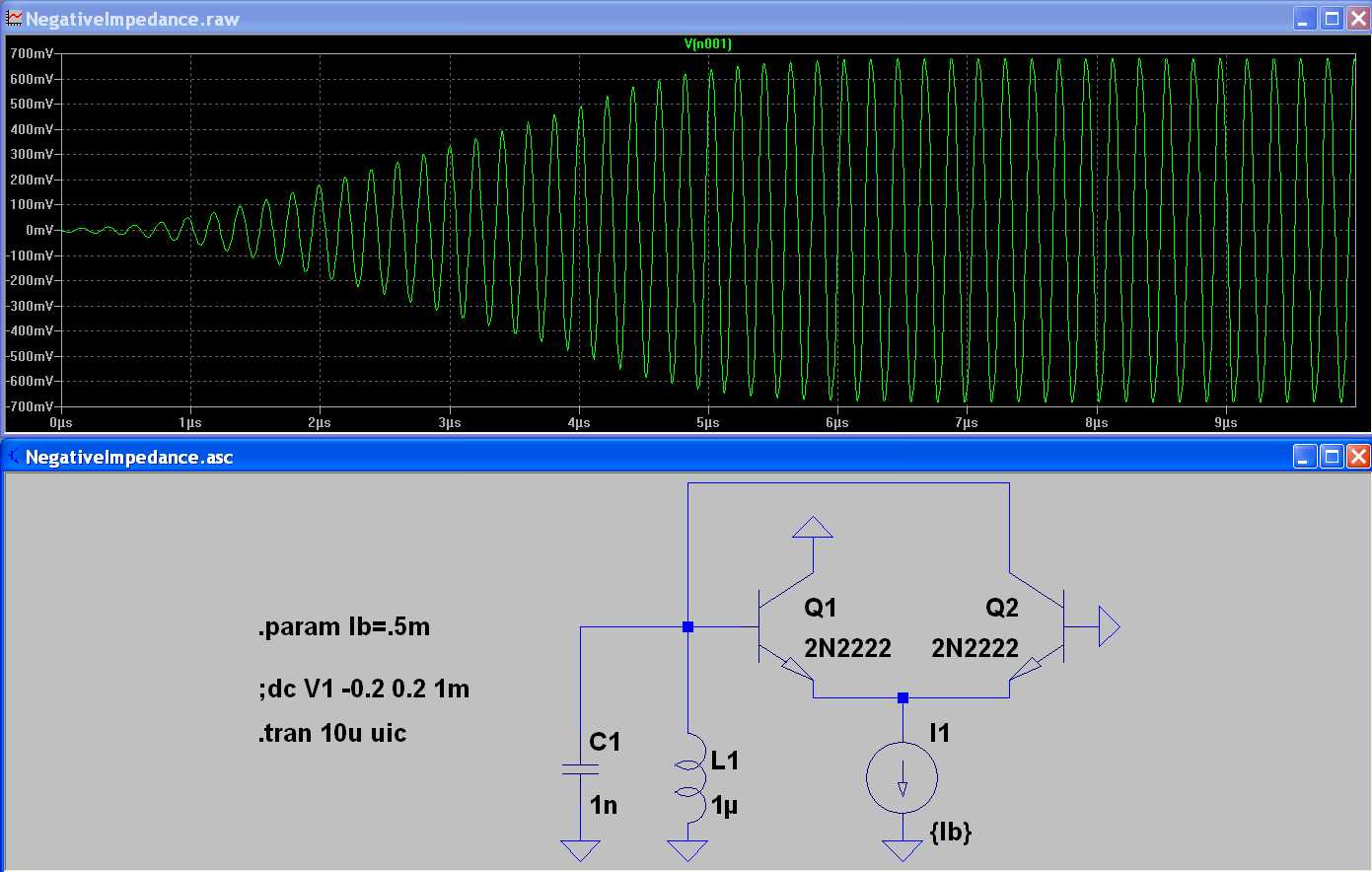
The impedance range is ohm to kohm. Unfortunately, it won"t work at high MHz or even GHz frequencies, because circuit reactances (junction capacitances and layout inductances) dominate the behaviour. You'll still be able to generate a negative impedance for a particular circuit node, but in a very restricted range and accompanied by a reactant impedance component.
Referring to the original question, what's your intention with negative impedances?
P.S.: The difference between a partially negative slope and a negative resistance in large signal behaviour matters particularly for a two terminal device, because a true negative resistance would imply an internal energy source. For an active circuit, it's easy to shift the negative slope part of the characteristic to the origin by applying a current and/or voltage offset. In so far, the difference isn't that fundamental.
Goldsmith, perhaps the following can improve your understanding:
Each oscillator with feedback (a so called "four-pole oscillator") can be also seen as a "two-pole oscillator" based on the negative resistance principle.
Example 1: Well-known Clapp oscillator. It can be analyzed based on the feedback principle as well as on the neg.-resistance principle because the differential input resistance with reference to the common base node is negative.
Example 2: The classical WIEN oscillator (opamp based) has an input resistance at the non-inv. opamp terminal that is negative (at a certain frequency).
Dear My friends!
Hi
one of my professors in university said that the oscillators are in two group : negative resistance and positive feed back.
I think that the things that he said are wrong. but how can i demonstrate to my professor that the positive feedback can generate the negative impedance?
Thanks for your attention.
Goldsmith
If you refer to a Gunn diode, it implements negative impedance without obvious positive feedback, although a semiconductor physicist can possibly show you, where positive feedback happens inside the device. But the well-known positive feedback oscillator circuits are always creating negative impedance at some circuit node, as various contributors have shown in the previous discussion. A simple example is the two transistor circuit from post #16.
In so far I tend to say both are two sides of the same coin and don't see a purpose of sorting oscillator circuits into two groups. On the other hand, if someone wants to categorize oscillator circuits, I don't feel a need to fight him as long as he don't claim obvious nonsense. E.g. if he tells, that positive feedback is opposite to negative impedance.
Dear FvM
Can you demonstrate with mathematical equations? for example for hartley oscillator . it is interesting for me .
Thanks in advance
Goldsmith
impedance generation 相关文章:
- Output Impedance Of a Triple cascode
- How to make image impedance equal
- Input and output impedance matching in Distributed amplifier
- Characteristic impedance of combination of CPWG and stripline on inner layers
- Problem of impedance matching of Gilbert cell mixer
- Input impedance of transmission lines connected in cascade