This LED SWR meter any good?
Thanks.
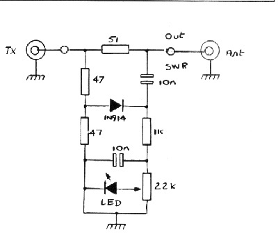
The circuit it will not work as a SWR meter, because there is no directivity in the coupler used.
You need a transformer or coupled lines to do the job.
Here is an example:
http://www.py2mg.qsl.br/Arquivos_PDF/PONTESWRQRP1.pdf
Thanks for the reply. It just goes to show that people place bad /non-working schematics on the internet.....why they would waste their time I will never understand. I have everything for the schematic you told me to look at. The 10pf trimmer is used for fine tuning? Anything else you can tell me about this circuit before I build it? Usage/design etc....
Thanks
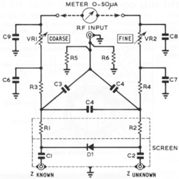
Looks like a bridge circuit to me, which could be used to measure the load impedance.
Bridge circuit - Wikipedia, the free encyclopedia
before you start building, you should really tell us what freq you are interested in using the meter on
yup exactly and you wont measure SWR with a bridge ! :)
OP have a look here for a real SWR meter :)
VK5AJL - Build your own micro-stripline SWR meter - the only way to measure SWR.
Dave
That link was perfect. Very informative. Thanks.
Not during regular operation, of course. You would use a coupler for that.
But as a "measurement instrument", bridge is fine (and broad band) to measure antenna input impedance.
"But as a "measurement instrument", bridge is fine (and broad band) to measure antenna input impedance. "
So If I was to make that bridge, I would connect it to my transmitter and antenna and it would let me know if the antenna is a good match for the transmitter by the LED not lighting up?
The configuration is not a bridge. Is just a simple diode detector followed by an LED which will indicate just the peak forward power.
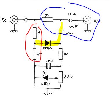
You can see here a simple impedance bridge.
Red = one arm of the bridge
Blue = other arm of the bridge, consisting of 51 ohm and antenna
Diode is between the arms, and will see RF power if the bridge is out of balance (i.e. antenna <> 51 ohm)
Rectified signal will then light the LED
- Ansys HFSS : Failed to solve port 1, solving at too low frequency is a possible cause
- design and simulation of cross-coupled VCO using keysight ADS
- Adding an indicator LED on RF generator, where should I?
- [moved] Fully Cross-Coupled Rectifier Configuration in Terms of Transistor Terminals
- Why do Infrared LEDs come with different coloured lenses?
- Microstrip coupled lines