Lossless Feedback Amplifiers
Anyone?
I would not call it a "lossless feedback amplifier", but instead call it a "tranformer feedback amplifier". It does not oscillate because the feed back is negative feedback.
I used a circuit much like that for a 140 MHz IF amp once using an MRF581. It was very reliable. no oscillations, high IP3 point, etc. It does suffer a little in noise figure from the feedback effect.
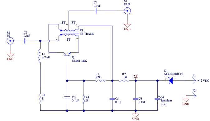
A agree with your comment "Transformer feedback". Also I posted the wrong image. I've seen where the transformer is attached to the emitter and fed into the base and where the transformer is attached to the collector and fed into the base. Would the inductance on the base be a stability problem for CB?
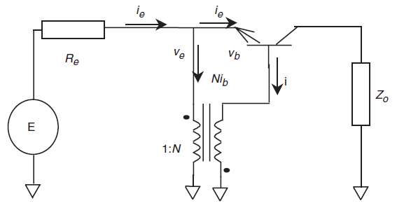
While the first circuit provides a reasonable shunt-series feedback scheme, the purpose of the second circuit doesn't seem obvious to me.
P.S.: Considering the fact, that NE461 is a microwave transistor with fT > 5 GHz, oscillation free operation of a transformer feedback may be somewhat questionable, I fear. Or you'd at least need to make a very small transformer.
Thanks Biff & FvM. The second figure came from an IEEE paper, "Operating limits for distortion reduction by the augmentation technique in nonlinear transistor amplifiers, N. Tilston, A.D. McLachlan and A.J. Sangster. Is it ok to post it?
High fT makes oscillation sometimes sometimes difficult and cost a little noise figure but seems to give better IMD performance and more bandwidth. I've used the BFG591 in the past but this time need unpackaged die due to size constraints.
This is a Norton amplifier first described by David Norton in 1975. By definition use negative feedback avoiding in this way the oscillation.
Here is a nice document describing its functionality and performances:
http://www.thegleam.com/ke5fx/norton/lankford.pdf
Does anyone have a copy of the Norton paper? I'm not finding it on the web.
All feedback systems have the potential for oscillating. The trick is to reduce the amount of feedback before the total phase shift goes 180 degrees. This transformer feedback method was invented many decades ago by a US company that made amplifier modules. It was patented. They called it lossless. Prior to that the usual method was a series resistor in the emitter and a resistor base to collector. The latter resistors added noise and the modules had 6+ dB noise figures. The transformer method usually produced a 3 dB noise figure.
Reverting to the distortion reduction augmentation technique. it's not a regular feedback circuit with feedback path from signal output to input, I think. In contrast, the transformer feedback is applied to a common collector configuration and has apparently the purpose to reduce the amplifier input resistance and remove distortions introduced by the non-linear Vbe characteristic.
As a supplement, here's a patent application describing the "augmentation" circuit.
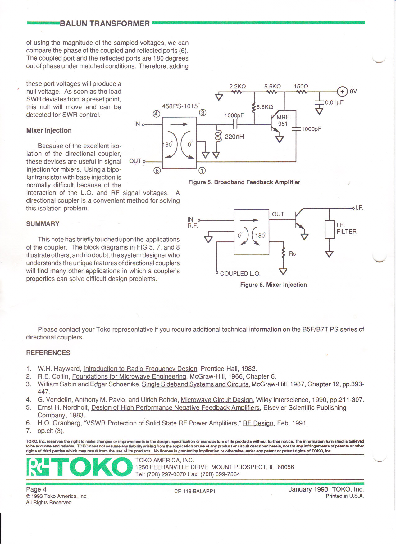
Was cleaning the office, and this app note fell into my lap. Toko CF-118. It shows the circuit I was talking about, but with an mrf951 transistor.