Feedback oscillator using BPF
时间:04-05
整理:3721RD
点击:
Using a conjugately matched transistor and bandpass filter in the feedback path, adding a transmission line between the two made loop gain >1 and angle near to 0, but HB simulation in ADS says Nyquist criteria not satisfied. How to proceed fixing/debugging this oscillator circuit?
if you meet the barkhausen criteria above, it will start to oscillate when the loop is closed. I have built tons of saw oscillators this way empirically using a network analyzer.
Now, if your active device shifts phase too much as it compresses to the devices final operating point, then you might have a problem with the oscillator not sustaining oscillations. Depends on how much excess gain u have in the loop.
BTW, a multipole bandpass filter will offer better phase noise than its 3 dB bandwidth suggests since there will be significantly more phase slope at resonance. The steep phase slope is a frequency restorative force. The leeson equation will have to use a Qeffective to work properly. Your problem with multipoles might be keeping them all tuned to the same frequency if the temperature changes.
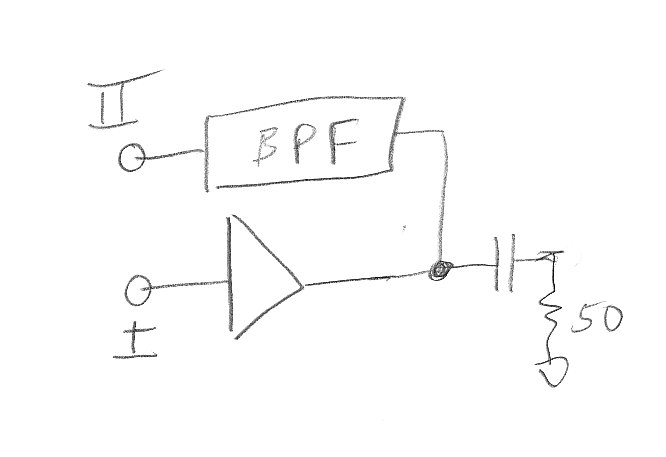
Above I just assume a single capacitor, perhaps of -j150 ohms, as a coupling to the outside world
Loop Gain>=1 and Closed Loop Angle=0 but there should be negative sloped zero crossing.It's not sufficient to get 0 degree Closed Loop Phase..
ADS look at it first..(You oscillator will probably work in reality but)
well, I would break the loop, see if the "open loop" gain is S21 >> 1, and the phase is near zero degrees. That way you are assured the oscillation will start. By open loop I mean u connect the BPF and active device in series, making a 2 port device, including whatever coupling device are using to get power out of the oscillator. Such as this:
if you meet the barkhausen criteria above, it will start to oscillate when the loop is closed. I have built tons of saw oscillators this way empirically using a network analyzer.
Now, if your active device shifts phase too much as it compresses to the devices final operating point, then you might have a problem with the oscillator not sustaining oscillations. Depends on how much excess gain u have in the loop.
BTW, a multipole bandpass filter will offer better phase noise than its 3 dB bandwidth suggests since there will be significantly more phase slope at resonance. The steep phase slope is a frequency restorative force. The leeson equation will have to use a Qeffective to work properly. Your problem with multipoles might be keeping them all tuned to the same frequency if the temperature changes.
Above I just assume a single capacitor, perhaps of -j150 ohms, as a coupling to the outside world
Feedback oscillator BPF 相关文章: