how to understand non conservative field
The professor shows us a amazing results.
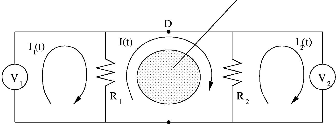
The two voltage meters are read different results.
And the note can be download from the follow url.
http://ocw.mit.edu/courses/physics/8.../lecsup315.pdf
My question is that if we connect the voltage meter penperdiculor to the circuit plane. what the result is.
thanks.
it is a so interesting problem.
If you flip the entire circuit by 90 degrees so that the circuit plane is parallel to the H vector, then it will be a conservative E field in the loops and simple Kirchoff law will apply. The integral of B dot dA will be zero as the plane will be parallel to the magnetic field, therefore the flux and hence the emf will be zero and the AC magnetic field will not interact with the circuit. Gotta luv Faradays Law ;)
Have Fun
for those engineers and physicists in the crowd...

BTW, tallface has it right.
My question is that if we connect the voltage meter penperdiculor to the circuit plane, and the circuit plane is still in the original way. what the result is.
Changing the orientation of the voltmeter won't change anything. What's happening is that the central loop of wire (and resistors) that surrounds the magnetic field (shaded area in the middle) is having an voltage impressed upon it, due to the location/orientation of the magnetic field. Since the magnetic field is perpendicular to the wires, it will have a net positive effect. By putting the wires of the circuit in parallel with the field, the net effect will be 0 V of impressed emf. The exercise is to show you have an H field effects a wire loop in proximity to it.
I have the answer myself.
There is no voltage concept between two point in non conservative field.
because when we walk through different path, the voltage will be different.
That is the critical thing!
understand conservative field 相关文章:
- Trying to understand mismatched antenna behaviour above 20GHz without equipment.
- Help in understanding the paper "Understanding Wide-band MOS transistors"
- Understanding of noise figure
- Need help understanding an LNA design method
- Understanding how to translate standards to system requirements
- Is it right to understand the Zopt(optimized noise impedance)of ind degenarated lna