How to get Desired Axial Ratio from Circular Polarized Patch?
thanks in advance.
Regards
JD
If you have an axial ratio of 20, you actually have a linear polarized antenna, as it should be 1 (0 dB) for a circular polarized antenna. What type of antenna and feed system do you have (you may post image)?
There seems to be problem with your matching feed. Make sure to create 90 deg phase diff. If you can share type of ant and feed may be some soln. can be found.
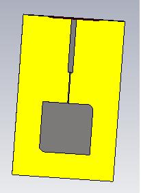
I Fed with a Quarter-Wavelength Transmission Line with truncated corners but i got Axial Ratio 20.
Regards
Junaid Iqbal
Corners are not truncated much. In order to get 90 phase shift, you need to truncate more to generate 2 separate X-Y resonant modes such that when fed between each axis you can get more circular quality with desirable axial ratio of 3dB. Consider truncate corners by 25% and feed off-center.
more general info but not 1/4wave http://www.orbanmicrowave.com/The_Ba...h_Antennas.pdf
http://www.orbanmicrowave.com/images...grated_LNA.pdf example of circular path, bottom feed.
Better design two orthogonal antenna with diversity switch to choose best.
Dear sir.
How percent i truncate the corner of patch?Will i compare the truncation with it's width or length?
Regards
I believe generally it is the longest mean path. so corner to corner for truncated corner patch.
I try my best but still i couldn't get desirable Axial Ratio? Please help me out that what can i do with that?
I will be thankful to you all.
Regards
Junaid Iqbal
Try here http://bit.ly/HJqE4E