Looking for dimension antenna 2.45GHz and dimension feeding
c= 3E8
dielectric=4.9mm
h=1.568mm
fo=2.45Ghz
please anyone helps me..................
really2 need help somebody.
my email djbink92@hotmail.co.uk
whats your problem
I looking for FR-4 patch antenna. I try design hundred time still not achieve it. I am using CST 2009. I just only want a dimension to me fabricate.. helps please..
The unit does not look right. You mean dielectric permittivity = 4.9.
Patch antenna calculator: http://www.emtalk.com/mpacalc.php
hi i attach a model for u and in hfss if u have HFSS 11 u can convert it to CST and simulated in HFSS we assume with 4.4 but in CST is 4.9
yes. I try to make patch antenna. this is design had done yesterday. By the way, I achieve 2.6GHz. I want 2.45GHz. I think its a problem at material of FR-4. am I right?
can anyone check what are the problem on my design.
i CANT to upload my cst files here.. :(
zip them and upload them and for that condition you should increase the size of antenna
Then scale your patch dimension by factor 2.6/2.45
And be aware that FR4 has large tolerances - you will measure a different resonance frequency than simulated, depending on the properties (fiber/resin mixture) of the FR-4 material that you use.
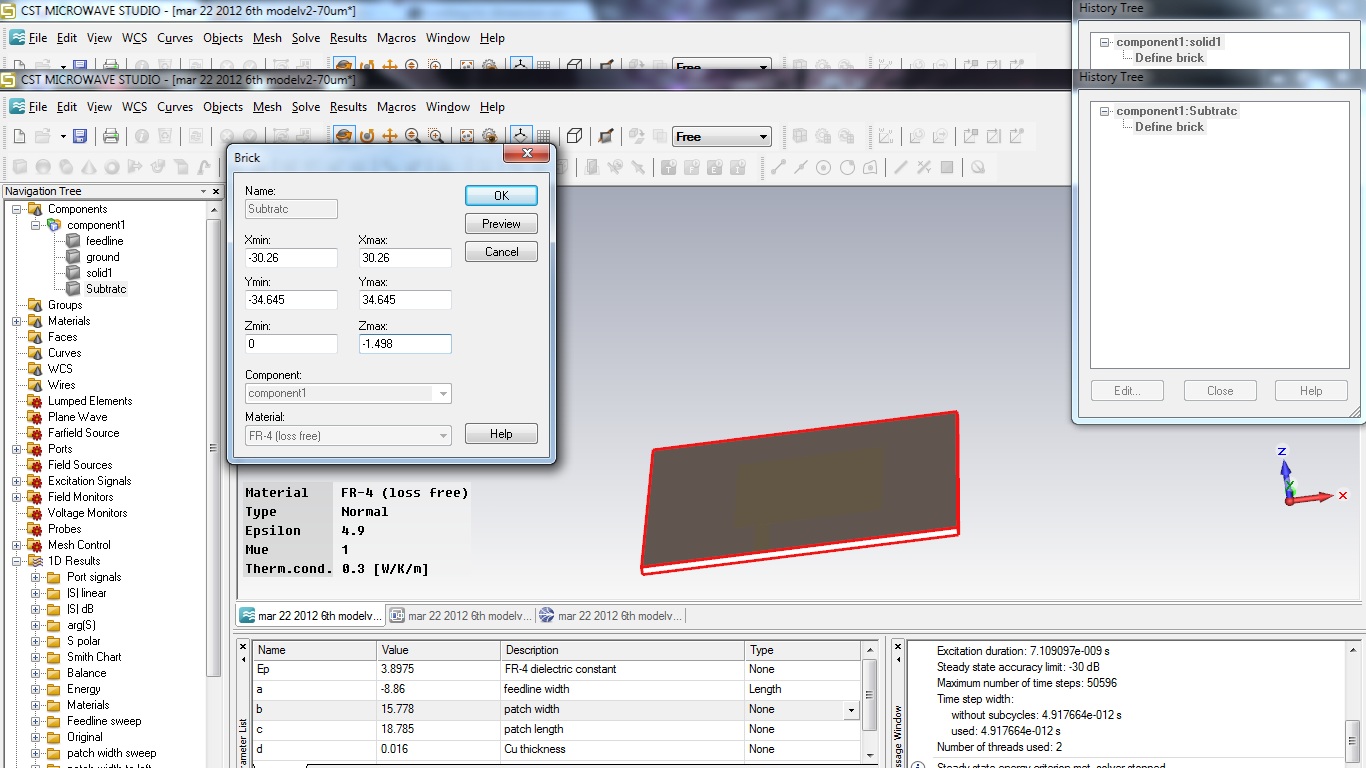
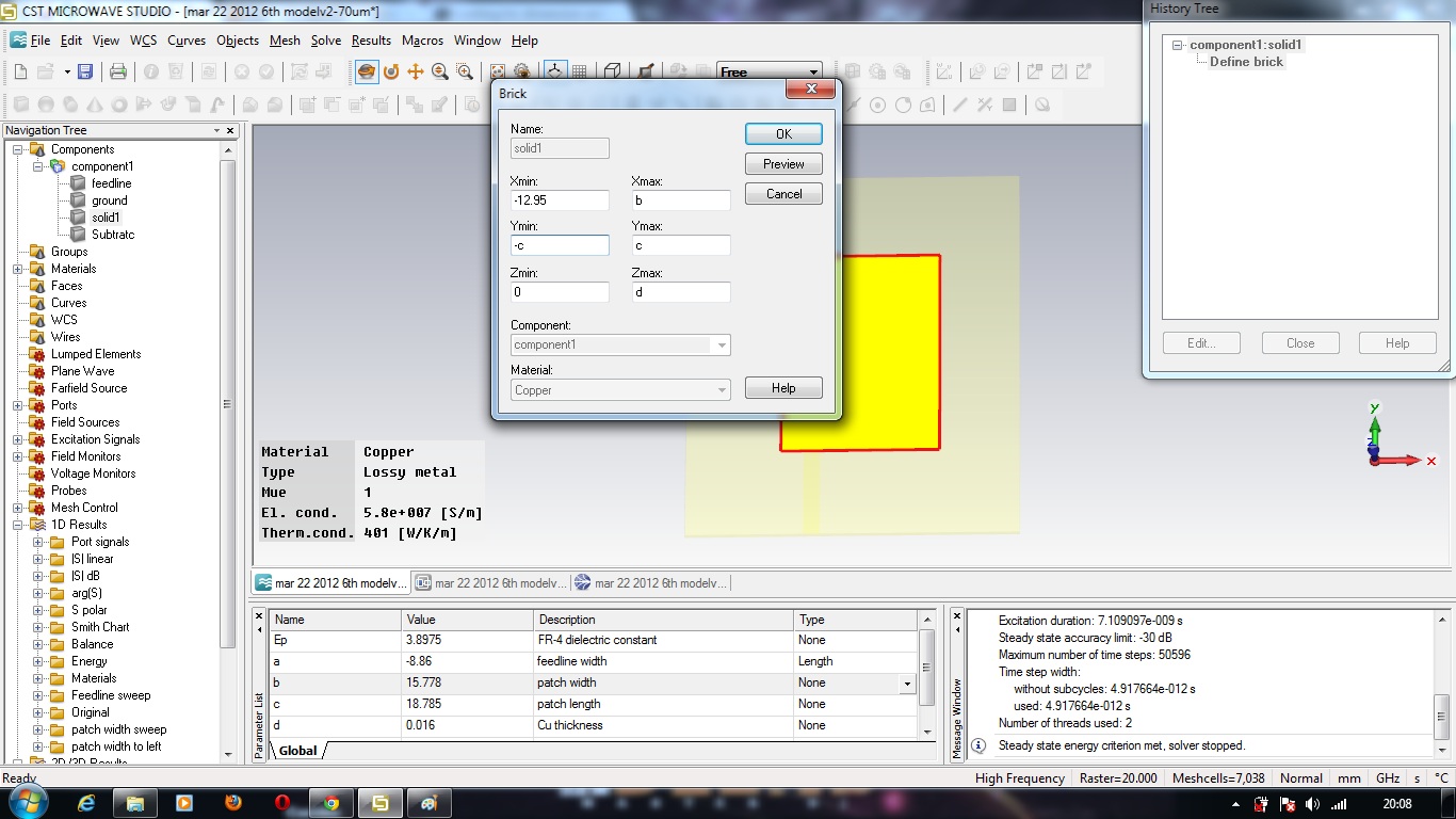
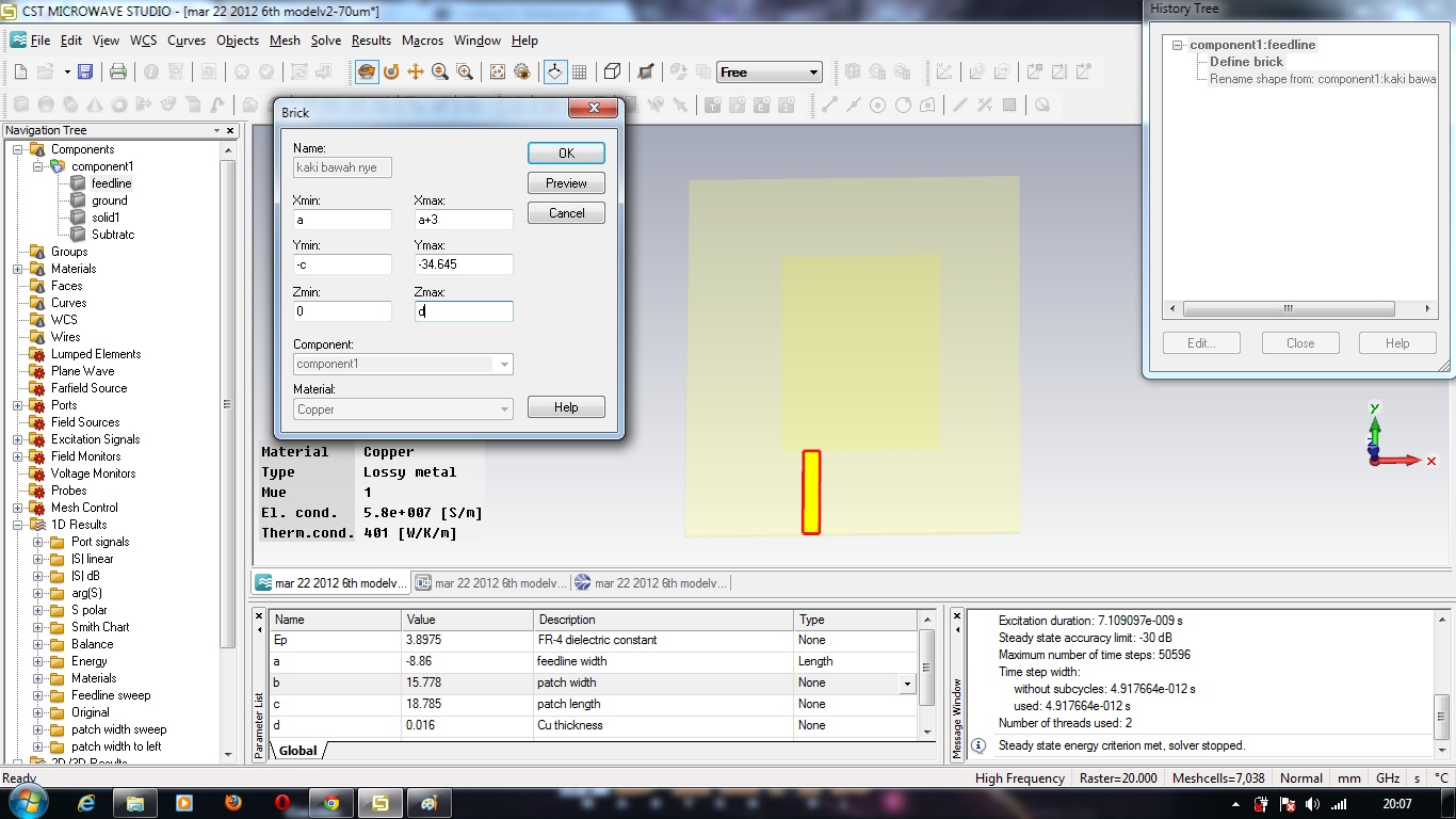
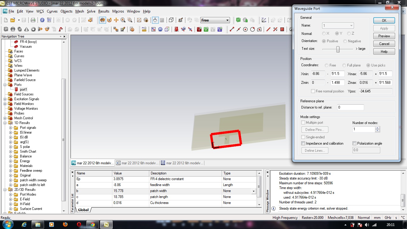
This is my successful design antenna using CST.
This just to share and if anyone have any suggestion to improve it, can email me at my email djbink92@hotmail.co.uk
I am using FR4..
Copper thickness = 0.016mm
Subtract= 1.498
Total Height of board=1.53
dielectric=3.8975
What the of type of this FR4 board? anybody know it?
I had fabricate it and achieve it.

antenna 2.45GHz FR4.zip
Why did you use this value?
FR4 permittivity is in the range 4.2 .... 4.9
owh. I wrong write there.. iam soory. the 3.8975 are for Ep.
Yes, that is the permittivity. The value looks wrong to me. It seems that you started with 4.9 from the material library, and then changed the value?
yes2.. because I have the board from PCB Lab with wrong description. I does not have any technical spec for the FR4 board. at the cover plastic from factory wrote the thickness of the board was 1.60mm.. however, when I measured it, its was only 1.54mm.. I had fabricate it. and I I does not get. and I try do again change the value of permittivity, and increase the width of patch, I get it value 2.45GHz. I will post the graph of real on the PCB board as soon as possible. hehe :)
That's not a problem. The difference is not relevant, compared to the other tolerances in FR4 electrical properties.
To tune the resonance, adjust the length (not width) of the patch.
The value for permittivity that you have tweaked can't be correct. You might have other errors in your model.
---------- Post added at 19:42 ---------- Previous post was at 18:17 ----------
Looking at your screenshots, I just realize that you feedline is not centered. Why did you insert that offset?
I adjust the length first, but its nothing happen to my antenna.. thats why I adjust the width..
what are the error you mean? I had fabricate it on board. Its working. hehehe :)
When the feedline at a center point, its can't achieve 2.45GHz. I look at my graph.. That why I put it on left. Have you had any design for PCB antenna 2.45GHz with the dimension for refer to improve its.
For your information, this antenna for my project RF Power Harvester. I want to make one project that from WiFi frequency 2.45GHz can generate DC voltage. Have you have any easy circuit from RF to convert DC Volt?
Iam just only a student. I study diploma electronic engineering ( instrument process & control ) at Politeknik Melaka, Malaysia. I just a student 20 years old. hahahaha
Iam very interested to continue my study after finish Diploma in Degree RF Microwave.. Now I am doing internship for 6 month at Universiti Teknologi PETRONAS. On my internship here, I really hope I can finish my project before 18 May. This project will encourage me to study more and learn more.
Thanks you for help me..
A.Aziz
https://www.facebook.com/aziz.bing
hi i attached the u desire antenna
my contact: ferdows_j@yahoo.com
thanks you for your antenna design. When I run it, its too many error.. why ea?
I want to say very2 thanks you to you for help me. hehe
However, you have another design PCB FR4 antenna in cst files for more power gain antenna work on 2.45GHz or dual band anything else.
like this picture