bias network instability
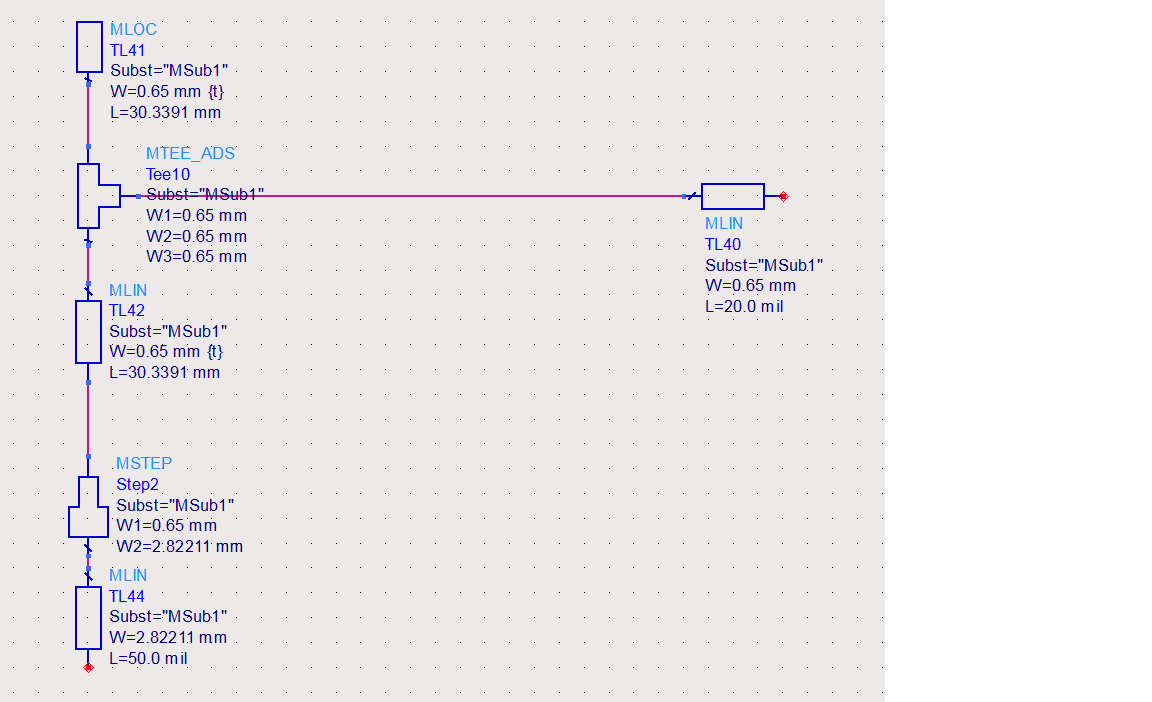
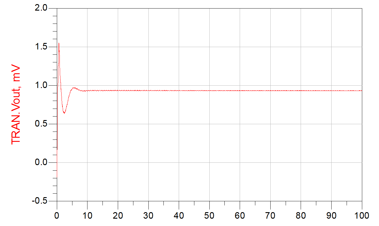
I have a question regarding the biasing network of an LNA. K have designed for un conditional stability (Rollet and Stern criteria) and when i perform an S parameter analysis everything is fine. However when i perform a transient analysis, my bias network seems to perform a small oscillation at about 1 GHz and this is transferred to the output (port 2). I am using a quarter-wave open stub and another quarter wave to perform the biasing operation. i attach the biasing network and the response..
Some active devices like LNAs sometimes tend to oscillate when the DC voltage is connected or disconnected. If the real device stabilizes at a correct operation point, then it should be OK. Some devices need two or more different voltages to operate, then you could design also a timing procedure for the best results.
With real LNAs, oscillations often occur with the input mismatch. If the oscillation would not occur in a correct operation point and with in/out ports matched, do not worry. If such short burst might affect the following stages, consider powering them after a delay.
thank you for your response..but as you can see even when the voltage becomes steady, there is a small oscillation. it's not in a particular frequency but it seems like random noise...will that be ok?
What I can see in the plot is not a RF noise or oscillation, but a sampling pulse train of your ADC. You could possibly see LNA noise after many dB of RF gain, depending on RF bandwidth before detector. I think you are on a safe side.
Try to put radial stub instead of simple choke. Radial stub has effect of capacitor and it not only suppress noise from the source but also provides good isolation.
with radial stub it gets even worse...i don't know what to do... the transistor is stable at all frequencies..
1) Can you post the complete schematic?
2) 50mm is kind of long.
Guys i found it finally. It didn't have to do with bias stability, but i had used a corner that was creating a parasitic mode at 500MHz. I used a bended transmission line and worked ... So as a lesson from all this fuss.. Avoid corners and generally anything that affects continuity abruptly. Every transition has to be done as gradually as possible. thank you for your help!
Congratulations. Layout has got us in trouble more than once. Mitered corners is typically used at RF. It's odd that a sharp corner would be impacting you at that low of a frequency (500MHz) but what ever works.
personally i think that this frequency was generated in a MSTEP that i had used at another point and this edge was acting like an antenna that was catching the parasitic signal...i am not sure though... i am relatively new to the subject of RF/Microwave design..can you please suggest me any references that explain these kinds of phenomena from a practical point of view? thanx in advance.