Question about biasing network of simple RF amplifier
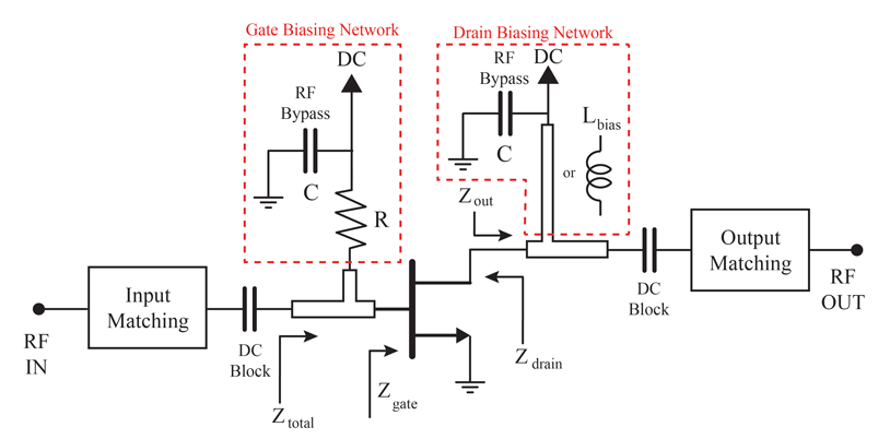
In this biasing network, what is the RF bypass capacitor for? And what is that resistor R for? My understanding is that the capacitor will prevent RF signals to go to DC source. Is it correct? Somebody told me that the resistor can help with the stability of the amplifier especially at low frequency. Is it also correct?
You are basically correct. Consider what the circuit looks like without them, there would be additional inductance at the top of 'R' and at 'L bias' which would be difficult to factor into design. The capacitors present a low impedance (AC short to ground) so making the effects of R and L more predictable. They also help, as you assumed, to prevent signal passing that point to and from the supply connection.
Brian.
Hello,
I'm just curious about this. at the input of the gate, won't the signal see a short. How will the gate sense the signal?
I'm not sure where you mean. There is no short at the gate.
Signal passes through the matching network, through the DC block (lets AC through) and into the gate through the inductor. It isn't clear from the diagram whether the stub is for matching or is a choke to the signal. The DC bias to the gate passes through the 'R' which also serves to isolate some of the signal.
Brian.

Thanks for your reply. I have another question. In this picture, I was told that the fan shape stub is a quarter wavelength open stub, which makes a short at the DC feeding point for RF signal. Is it also going to prevent the RF signal to go to DC source? If I have this structure, I think I've already made a short at the DC point. Do I still need RF bypass capacitors?
First think of the lambda/4 stub being replaced by a conventional transmission line. RF (AC) signal is thus presented a low impedance path into the DC power supply. Not good.
Now using the lambda/4 transformation: The RF signal (at base & collector) is presented high impedance (Z_RF=infinity) and this prevents RF (AC) currents from flowing into DC source. (For the biasing DC the lambda/4 is of course only a conductor).
The radial stub is used (additionally) because it offers superior performance compared to low impedance quarter wave microstrip. You basically want to have your quarter wave to be as wide in bandwidth as possible. This can be achieved by using low impedance microstrips. But the wide t-junction will lead to S11 problems. So you try to use a "normal impedance" quater wave microstrip which is not very wide in bandwidth but will not harm your S11. At the end you place a radial stub at the end (which has a wide bandwidth).