impedance of the PCB balanced line of a balun with a complex impedance
Thanks in advance
Although it's possible to perform the matching with line segments only, you'll most likely want a lumped element matching network due to room constraints.
As already stated above, tune out the imaginary part at the balun.
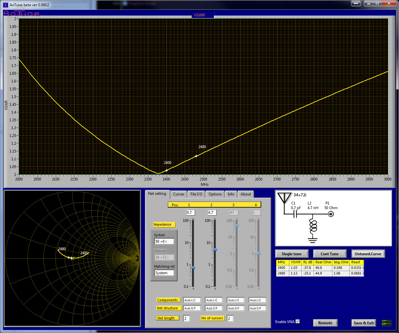
You can cancel the imaginary part with a 2.2pF series capacitor, to obtain 34 +j0 ohm input impedance.
Or use parallel + series C to match any real impedance between 34 and 186 ohm.
This is only theoretical values at BT frequencies. For the real application add corrections for PCB traces impedances, phase delay due to trace lengths, non ideal components and an antenna that only partly is close to 50 Ohm.
My general advise is to leave space for a matching network but wait to decide matching components values until whole Bluetooth unit including its normal environment can be measured with a VNA.
If you anyhow want to see theoretical matching results for a L-network:

