Transceiver circuit antenna component design function
My questions are:
1) What is L3 and L4 doing? Are they blocking high frequencies and passing DC? Or do the inductors have something to do with the matching, if so why?
2) Suppose I wanted to do some sort of digital step attenuation. Are there any DSA's that work with differential pair antenna lines or would I have to go with a BALUN approach if I want to use the DSA?
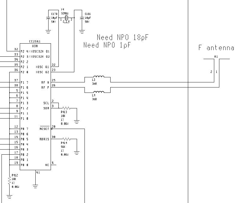
1-L3 and L4 are obviously matching components.They could be used to increase the effective length of the antenna if the antenna is simple half and unfolded dipole.
2-DSAs are generally single ended input/output circuits and therefore you should use a balun before matching circuit.But before doing this, you should know output impedance of the tranceiver circuit because if DSA is not matched ,you may loose some power.Because DSAs have been designed generally 50 Ohm input/output impedances that's why you should consider matching issues before and after DSA..
Lumped element inductors are known to have high loss. Should I use a copper trace length instead?
I found a differential DSA
http://www.skyworksinc.com/uploads/d...ts/200935F.pdf
although it does not have the correct spec (freq and atten level) differential DSA's do exist. As an alternative solution to the BALUN approach is it possible to keep differential antenna matching design and then place one single ended DSA on the positive line and one single ended DSA on the negative line?
You can surely use copper PCB lines instead of lumped coils but it depends on substrate dielectric coefficient.If you use use standard FR4 double sided PCB, these tracks will be pretty long.
I don't know it is convenient or not for you but it's possible to use copper PCB tracks on their places.Or you may also design these inductors as spiral or octagon shaped PCB coils.The second one is much better in term of practical application.Put the coils perpendicular to avoid magnetic couplings,otherwise common mode currents will create imbalancing between differential signals.
You can also use twin DSA or 2 times single ended DSA,both are possible but it's justc a problem of cost.
Pay attention matching between the components and study on the input and output impedances to obtain the right power level.