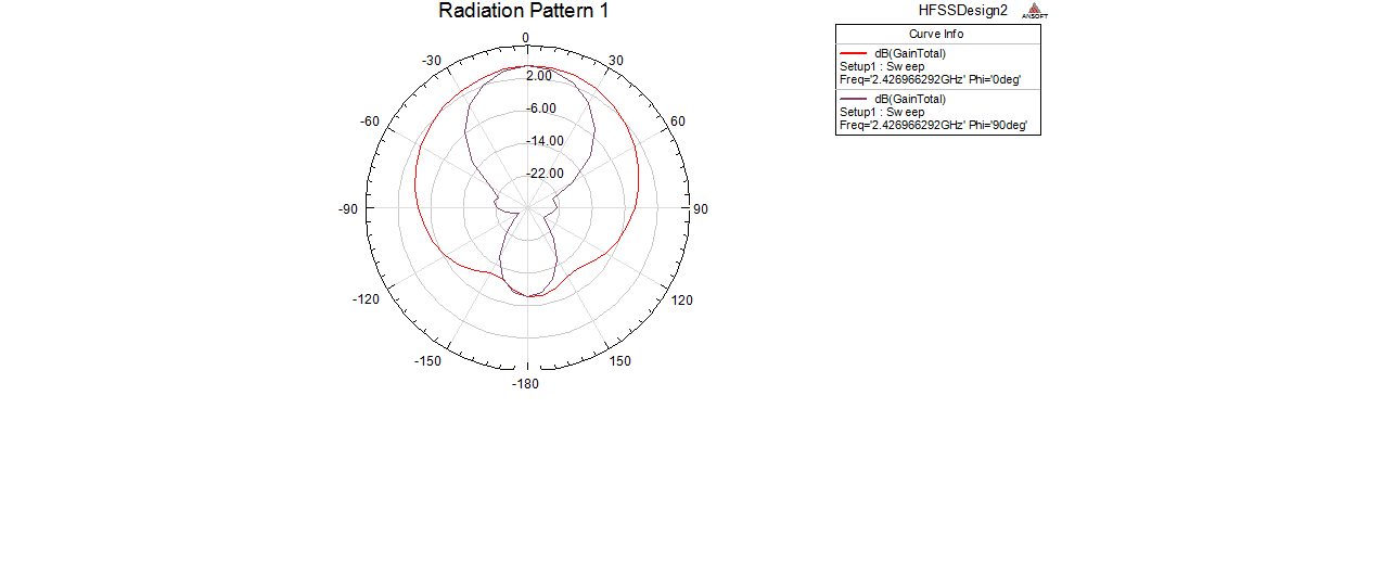
reduction of back lobe in patch antenna array
时间:04-06
整理:3721RD
点击:
operating freqeuncy=2.4ghz
substrate is FR4 dielectic constant =4.4
height=1.5mm
lamda=60mm
distance between each patch=lamda/2=30mm
T-junction power divider is being used.
simulation is done in hfss
for 2 array,gain=5.5db and directivity=9db at 2.4ghz
I need some method to reduce the back lobe.
Why don't you try to use a reflector?
which type of reflector to be used and how to implement it in hfss?
Is it a simpler method?
I do not use hfss or modeling. I prefer making and testing antennas. Try the same.
BTW, if you "work on antennas", I assume you have an idea how a reflector looks.
Reflector? The patch antenna does have some back side metalization anyway, so that's more or less the reflector. Maybe the back side metalization is too small.
what type of feed are u using? Ensure that the feed is impedance matched
use PBG structure on ground plane :)
increase the size of ground
- What is the reason for minor lobes being formed in a directional pattern?
- quadrifilar helix antenna with backlobe
- Side lobes missing on radiation pattern
- Acceptable value for sidelobe levels in antenna arrays
- Assymetrically placed Close in side lobes
- mutual coupling sidelobes cross-polarization in microstrip phased arrays