VCO Tunning Voltage and Power supply
It won't probably be anything happen but VCOs have heating-up times and even tough tuning voltage is fixed, VCO frequency will be different at the beginning ON state and after a while..
So you want to say that if we keep the supply off and apply tuning voltage there might be problem of heating up?
Will there be any undue damage or not to the vco in this particular case, for the time being let's just ignore vco's frequency drift despite of fixed tuning voltage;
Applying tuning voltage without supply voltage is not a particular trouble, it doens't heat up the VCO .I'm just saying "if you apply tuning voltage without supply, the VCO frequency won't be same after a while because of heating-up nature of the VCOs.Many VCOs work by cutting off supply voltage but you should wait while to the frequency is settling down.
the question can not be answered unless you tell us what vco you are using. I am sure there are vcos on an integrated circuit that would be damaged by applying tuning voltage if the IC itself is not powered up.
If you are using a stand alone VCO with a varactor diode on the tuning port, as long as you have a current limiting resistor in series (say 220 ohms) you can do anything you want to power supplies without blowing the vco up.
Also, tell us how you're generating V.tune. Many PLL chips (ADI for instance) allow the charge pump output to be tri-stated.
The VCO is Mini circuits' JTOS-200. I don't know if its using a varactor diode.
- - - Updated - - -
- - - Updated - - -
you mean:
tuning voltage without supply: one frequency
tuning voltage with supply:(heating up) slightly different frequency
Does this mean VCO still produces some frequency output without power supply applied?
- - - Updated - - -
Current limiting resistor at VCO tuning port? Wouldn't it alter VCO tuning voltage?
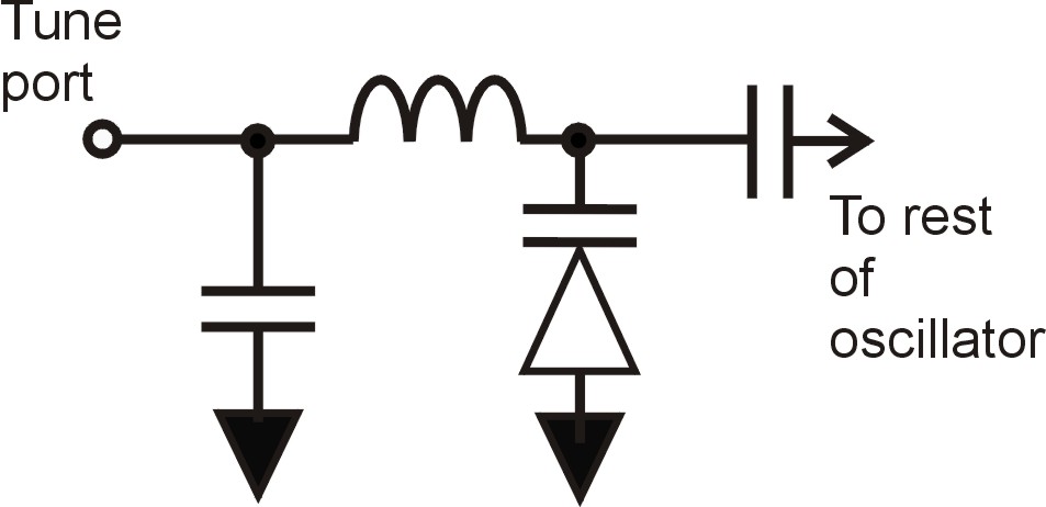
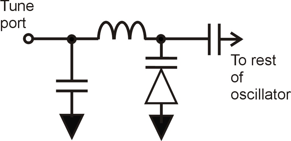
from the tuning curve shown for the JTOS200, I am pretty certain the tuning portion of that vco schematic is:

So as long as the VCO stays attached to ground, and the tune voltage is somewhere between 0 and +16V, you can not blow it up. If you were to do something (like putting -5V on the tune port without a current limiting resistor) to allow current to forward conduct thru the varactor diode, however, it would smoke it very quickly.
I know VCO provides output oscillations for a given input voltage.... it was told that VCO output oscillation can be controlled by a DC voltage... is the control voltage and input voltage the same and does supply voltage got anything to do with the output...also is it possible to only give DC input to VCO or even AC voltage can be given? Also could anyone please tell what is VCO tuning frequency... I thought VCO output is tuned by control voltage but what is this tuning frequency?
you should go to a website, like Zcomm's, and look over data sheets.
A VCO has an active transistor or FET in it, and that device needs DC voltage to work. So typically either 3.3 or 5 volts is applied to the fet drain or transistor, and a base/gate bias is derived to keep it operating roughly in its linear region for oscillations to begin.
But in another part of the VCO circuit is an inductor and a capacitor. They form an LC resonant circuit. Where the LC resonates in frequency, that is where the VCO frequency will oscillate at. For a tunable oscillator, they replace the fixed capacitor with a reverse biased diode (called a varactor diode). a varactor diode varies its RF capacitance as you apply different DC tuning voltages to it.
So a VCO has a DC power pin, and a Vtune pin, that are unrelated to each other

I went through Zcomm website u suggested... I understand the part that a DC voltage is given as power supply to operate in linear region... as seen in the figure I uploaded (5V- Vcc)....The tuning voltage Vdc is given to 0.50 to 4.50... so does this mean we set one particular Vdc value (between the range 0.50 to 4.50) to the VCO input and can be varied accordingly or is it like the entire 0.50 to 4.50 is given as a AC voltage to VCO input? Am I getting it correct or have I got it more confused? please help me out
look at this simple circuit again:

If your tuning port had 0.5 V on it, then a reverse bias of 0.5 V would be placed across the varactor diode shown. If the tune port had 4.5 V on it, then a reverse bias of 4.5 volts would be across the varactor diode.
Now imagine the diode used is an ON Semiconductor SCV710:
http://www.onsemi.com/pub_link/Collateral/ENA0605-D.PDF
When you applied 0.5 V, the diode capacitance would be 26 pF. When u applied 4.5 v, the diode RF capacitance would be 4.1 pF.
So by varying the tune voltage applied, the capacitance chages, and thus the resonant circuit of the varactor diode and an RF inductor (which would be in the "rest of the oscillator" part of the oscillator depicted)-- the resonant frequency would change. The higher the tune voltage, the higher the oscillating frequency.
And, from the schematic, one can see that if you applied a negative tune voltage, say -2 volts, that a +2 V forward bias would be placed across the varactor, and it might blow it up. Typically one puts a 220 ohm series resistor at the tune port to limit the current thru the varactor if there is a chance that a forward bias can be applied accidentally.
ok let me tell wat I understood... sorry if I wrong...
1. so basically to start the VCO we need a supply voltage just to begin the oscillations and keep it in linear region (DC power pin)
2. to control the frequency of oscillations generated we apply a DC voltage to (Vtune pin)... can we apply only DC voltage or even AC volt.. so in VCO is there only the case of DC voltage and no AC at all..... so this Vtune pin is where the input is given... am I right or wrong... or is the input given to another separate pin.. and the input voltage and control volatage of a VCO are the same or different..
I was going thro VCO based ADC and it was put that ADC resolution increases as a function of VCO oscillating freq.... so if its a function of VCO oscillating frequency we should change the input voltage (AC voltage in VCO based ADC as the input signal) since the oscillating freq changes with input voltage... in VCO is it necessary to change the input signal to VCO to change oscillating freq or can the freq be changed without changing the input voltage.....have I got it all confused? please help..
Also can u tell me what is VCO phase shift?
Most Block VCO's, as ones from Z-Comm and other manufacturers, are likely to have 4 pins
Vt Pin -- DC (ONLY) tuning voltage ( this could also be called the control voltage)
V+ Pin -- the power supply for the VCO
V0 Pin -- the 0V (Ground) pin
Out Pin -- the RF output pin
Dave
Thank u for the post.. So I can see that no AC voltage can be given to the control voltage(input voltage) pin... But when I read a paper abt VCO based ADC I saw the input given to the VCO was a sin wave so I got confused and output of VCO was a square wave which was proportional to the input sim wave.. Can I please explain why is it in this case...
- - - Updated - - -
Thank u for the post.. So I can see that no AC voltage can be given to the control voltage(input voltage) pin... But when I read a paper abt VCO based ADC I saw the input given to the VCO was a sin wave so I got confused and output of VCO was a square wave which was proportional to the input sim wave.. Can I please explain why is it in this case...
have you a link to that paper ?
cuz it would have to be more than a standard VCO if it is also is doing waveform conversion
Dave
It's possible and I've tried it with an x-band oscillator. Works without a problem.
When you switch the power of a VCO, the rising and falling edges of the switching signal should be as short as possible.
I've experienced, when there are slow rising and falling edges, VCO ouput frequency spectrum gets broaden. I think due to high phase noise and during the supply voltage transients it generates lower frequencies than the specified output with the applied tuning voltage.
cheers,
per_lube
when u attempt to turn on/off a vco you will encounter all sorts of troubles. There is usually a significant R-C rise time in the bias elements. The oscillator active device (and varactor diode too) will cool significantly when DC power (and consequently RF oscillations) is removed. It will take a significant time, once oscillations resume, for the active device and varactor to reach their normal operating temperature (see post tuning drift). It does not help that so many devices nowadays are in cheap plastic packages with horrible thermal resistances! Also, some oscillators may have metastable performance--they do not necessarily start up in their final operating state, and take some time to get there, due to device modes or possibly bias line resonances.
