inductance calculation
Is it an air core inductor ? In this case you can use the wheeler formula:
L(uH) = (D?N)2/(450?D+1000?w)
where D is the diameter of the coil, in mm
w is the length of the coil, in mm
N is the number of turns.
if w>0.4?D the accuracy should be around 1%
In case of magnetic core you could try to multiply by μr, but I don't know anything about the accuracy.
I think this fomulae is not for RF Coils, instead Ferrite Cored Inductors which are used for Low Frequencies.I presume that you're looking for a formulae for substrate layed down RF Inductors.
now i am confused which on is magnetic core and which on is air core?please somebody make it clear? in my case i need a circular coil to make a high frequency about 2mhz LC resonator ?
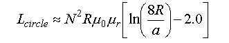
albbg .. yes my one is a air core inductor.but you have given the formula for cylindrical coil.but i need formula for circular coil.
OK, you are right; you could set w=diameter of the wire (if your coil is wire wounded), but if w<0.4?D the formula isn't so accurate.
Anyway, your formula should works. Could you please post the numerical dimensions (radius, diameter of the wire..) of you coil and, as said by BigBoss, if its printed on a substrate ?
RF Coils are hard to calculate because they suffer more from paracitics like mutual inductance, capacitance, skineffect, DC resistance, eddy currents etc.
Caps are also not ideal, they suffer from voltage- and temp-co, ESR and ESL. For instance X7R is not suitable for a resonant circuit.
I assume you are not using a breadboard.
Things like metal objects near a coil (eddy currents) or coupling to the rest of the circuit also pull the resonance away. For instance an instrument nearby. I measured pcb coils for a medical research for MRI use. The Q was over 1000 on 40 MHz and we managed to measure the unloaded Q very close to the calculated one. (I helped them with the VNA measuremnents and came up with the best way to measure. Someone else made the inductors and did the calculations.
In AC theory from D. Knight you find the correct formulas for resonance using complex impedance for parallel resonance, and in analog SEEKrets, from DC to daylight (L. Green) page 96 you find the formula from Nagaoka and the tables for the F factor he derived from Lorentz theory. Wheelers formula is a simplification from Nagaoka's work. Green also gives a formula that is more accurate (0.13% but everything depends on the circumstances, like material and frequency) Both books are free downloads and very good material and tell you everything about inductors and resonance there is to know.
Coils using core material suffer from a current cooficient (inductance drops if the current rises until saturatation) but aircoils also suffer a bit from this, but almost neglectable. (I have a 0.1% L bridge with pH resolution and then you see it but for a 3 uH coil this change is in the tens of nH range)
I assume you measure resonance not by probing straight on the tank circuit but after a buffer or through a EH probe or something like that ? The capacitance of your probe pulls the frequency down.
I used the formulas from Green to design the coils for a ten 7th order LPFs for 10 VCOs from 50 MHz to 2 GHz. And then measured the coils in situ at the working frequency with a VNA. The same way for the caps and microstrip parts. And after I put the parts together I only had to squeze some coils a bit and all 10 filters worked right away without using trim-caps.
Inducters are fun !
inductance calculation 相关文章:
- calculate mutual inductance of two close inductors from s parameters
- How can I get the crystal with low inductance
- Mutual Inductance WPT system of coaxial spiral coils
- Adding inductance to a slot
- Q-factor and Inductance Calculation from S11 parameter in 1 port mode
- Via inductance vs diameter at high frequencies.