Differential Transmission Line in Cadence (Behavioral Modelling)
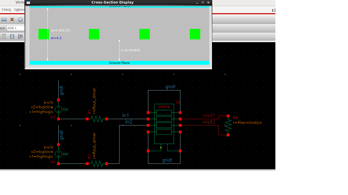
I am trying to model a differential transmission model for my lvds application. I first found out that for visual applications ribbon cable is the one commonly used for small distances upto 0.5m. I looked up the spec, dimensions and dielectric properties of the ribbon cable and modeled it using the strip line model of mtline. For a single pair of ribbon cable i used four conductors by grounding the two conductors at each side. I have attached the lmg gui for the modeled mtline for ribbon cable.
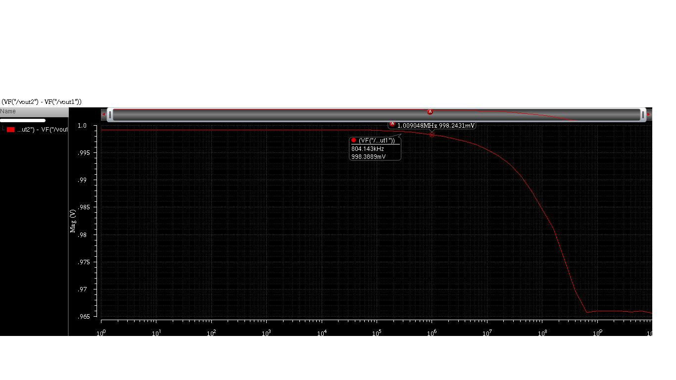
The response of my system is quite good and idealistic, which is bothering me. It has no overshoots and no ringing effect. System is perfectly damped. I have attached the AC analysis graph. I am expecting an output which can show me some overshoot, some non-ideality, some effect of the line inductance. But all i am getting is a perfectly damped response. With increase in frequency the resistive drop increase due to skin effect but the signal still remains overly damped with no overshoots. Can anybody help me sort out what thread in modelling i am missing over here?
http://obrazki.elektroda.pl/1719759200_1397494162.png
http://obrazki.elektroda.pl/7996752300_1397494162.png


Ringing, over/undershoots come from the mismatch of reactive
components / aspects to the resistive sources & terminations.
From what is shown, these are all ideal. So it's not surprising
there are no nonideal behaviors.
As a test, try skewing the termination resistance from the ideal
value. At (say) 2X or 1/2X you should see significant overshoot
(high Zterm) or staircasing (low Zterm).
I am unfamiliar with the mtline element, have only used the
simple tline. Maybe there's more to it. But I'd start with the
simple look at whether termination resistor value matters
(it had better) as a sanity check.
Dick,
One more thing. There are three models. Lossless, narrowband and wideband. I have not a lot of information about them. But from what i have studied, wideband seems to be the thing to go with. Plus i am writing the maximum frequency which the mtransmission line asks from me as 2Ghz(fmax), i dont know the significance of this parameter either. Which is my transmission speed.
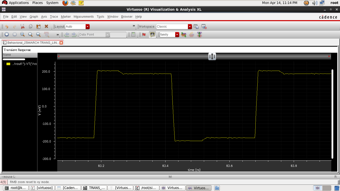
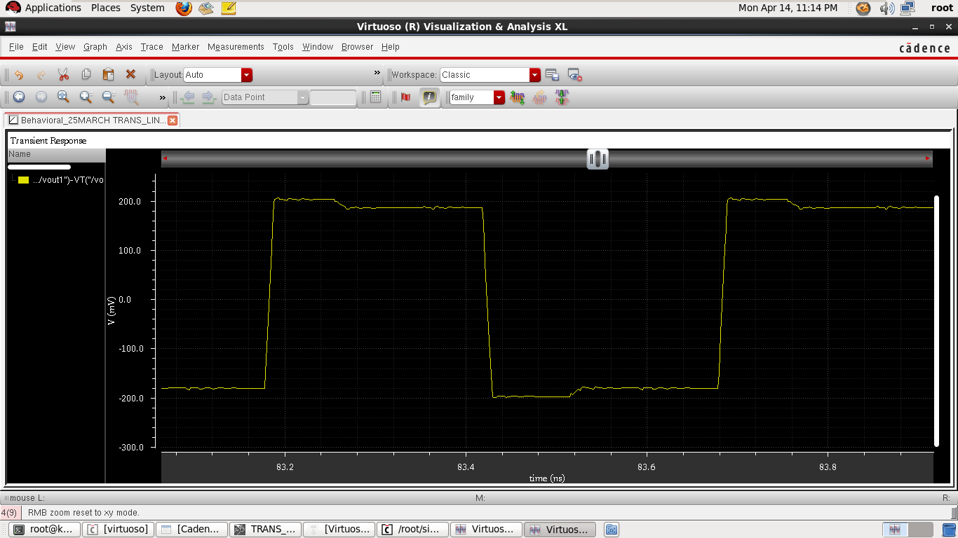
As you can see i have put two terminations, one at the load and one at the source end in the previous image. I've calculated the line impedance to be 50 ohms from an external field solver using the data i am entering. I am attaching the image with 50% impedance mismatch. you can see there is definite interference which cause the majority part of swing to cut down. But the reflections should not die down so immediately. Or should they. I mean the whole response look so resistive.

It's normal..
You're looking the output voltages differential and an effect that occurs on a line is occurring in inverse phase on the other line and these effect cancel each other.
In order to see non-ideal effects of a transmission line, you should do a transient analysis instead of AC simulation.Ans also transmission lines can be modeled with RLC components.
For you transmission line which is "Strip Line", you can apply the same approximation so distributed RLC components will represent your TL.
BigBoss,
I havent tried modeling the transmission line using a resistor and inductor in series and a capacitor and another resistor in parallel. I think i will do that today. But as far as running transient simulations are concerned, i have done that and posted the image in my reply above and still no non-ideal behavior is noticed. The problem remains, when rtermination is mismatched, reflections occur. But these reflections die down immediately.

I agree with your consideration that a wideband model must be used to model time domain behaviour of transmission lines. The cadence manual states that a frequency dependent LRCG matrix is used, which should basically allow a realistic simulation. Simple frequency independent LRC or LRCG models generally don't represent transmission lines correctly, e.g. the standard SPICE lossy line model.
For the present problem (0.5 m line), the analysis looks a bit like overengineering to me, a systematically correct differential transmission line impedance should do the trick.
Line Transmission Differential 相关文章:
- Response of the TLINE for different frequencies and lengths
- About Stripline design questions
- Heterodyne detection, non-linear mixer and minimum detectable signal (2-way radar)
- Linear cellular Power Amplifier without any load harmonic termination?
- How to plot Loadline in cadence spectre
- ABCD Matrix of transmission lines connected in cascade
