Calculation of Inductance of a coil around rod
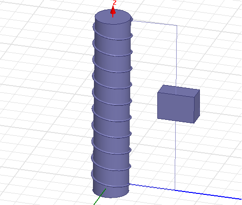
I have designed a coil around a ferrite rod. I need to calculate the inductance of the coil. I have taken two wires from the two faces of the coil and gave them to the face of the box as lumped port. The design of the coil is shown below.
The result of the parameter values are
s:1:1 Y:1:1 z:1:1
Freq 101.4 kHz 1:1(1 , 180) 234.16.-90 0.0042705,90
How can I calculate Inductance of the coil from this. Thank you in advance.
I presume, you have already heard how inductance, frequency and inductive resistance (reactance) are related. http://en.wikipedia.org/wiki/Electrical_reactance
The other question is, if your inductor is so small and the core permeabiliy is so low that a value of about 6.5 nH can be expected. Or if it's just an erroneous simulation setup. (There are some indications in your various same topic posts)
What are coil diameter, length, number of turns (apparently 10), core μr?
Hello FvM,
Thanks for responding, actually I need to design an inductor as shown above with 247 uH of inductance and later give resonance with a capacitor of 10 nF. This is my coil set up
The coil diameter is 1mm,
Length 300 mm,
No.of coil turns 60
and the Ferrite core μr is 1000.
Can you tell me how can Inductance can be calculated, thanks in advance.
You mean wire diameter?
Yes diameter of wire, actually mentioned above diameter is a rough calculation it can be change to 1-3mm it is not so perticular.
In other words, I was asking for the coil diameter.
For the air core inductor, you can use a popular web calculator as a reference. http://www.qsl.net/in3otd/indcalc.html
It gives e.g. 5.7 μH for 22 mm coil diameter
An axisymmetric simulation with core gives about 350 μH. (20 mm core, 22 mm mean coil diameter)
How to calculate inductance when a ferrite core is placed which has some relative permitivity? How can this found in HFSS using the parameter (S, Y and Z) values practically?
You need at least an 2.5-D AC-magnetic solver for an accurate simulation. HFSS should be able to it (not my tool), but apparently you did it wrong.
As I already mentioned, coil Z can be directly converted in inductance, Y is just the reciprocal value as you should have realized by looking at the numbers. S11 can be also converted to impedance, but you have too few factional digits to see it in your result. All numbers in post #1 are void because the simulation is obviously wrong.
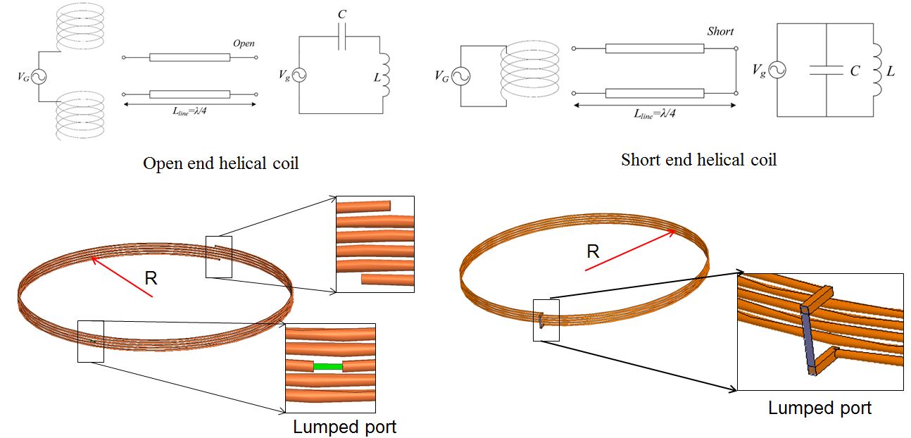
Hi FvM and everyone, can you help me?
I have a helical coil with open end and short end as showed below.
For helical coil, we need to take into account the stray capacitance of coil.
So, how can I have the value of L and C, separately, using HFSS
Inductance Calculation rod 相关文章:
- calculate mutual inductance of two close inductors from s parameters
- How can I get the crystal with low inductance
- Mutual Inductance WPT system of coaxial spiral coils
- Adding inductance to a slot
- Q-factor and Inductance Calculation from S11 parameter in 1 port mode
- Via inductance vs diameter at high frequencies.