Identify this transistor?
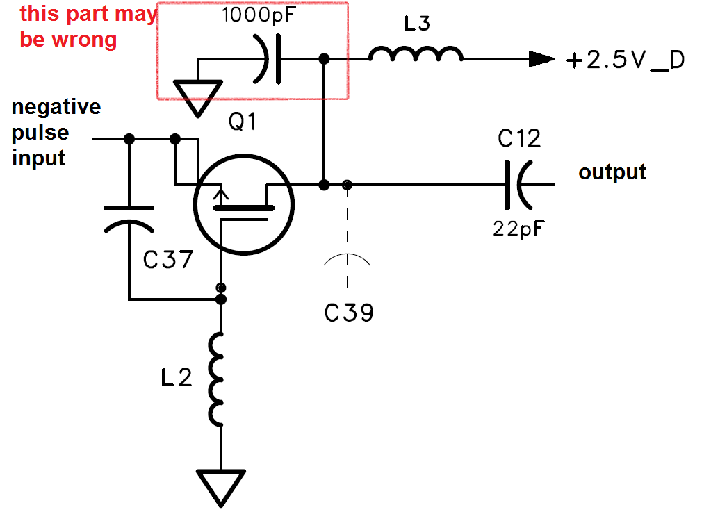
I'm having a hard time identifying this transistor. From the circuit function and layout, I figured that it is an oscillator working around 2 GHz. There is a little piece of transmission line connecting the gate to ground. The drain is biased at 2.5 V and the source is pulled down to -1V or so to turn on the transistor, and then oscillation starts until the source is returned to ground.
Any help is appreciated!

From the picture I can't read the marking code. What code is written on the transistor ?
I think it's either "On" or "Oh"
Have you got a more clear picture of the component ? However it seems to be a diode, since it's labelled as D6.
Sorry I saw now the component is the white one.
Yeah the white one is what I'm talking about. It is labeled Q1.
I'll try to take a better picture; need to find a better camera...
I believe it's a microwave transistor. Example, MRF-901.
Your picture shows it's round with 4 terminals. Almost exactly like the transistor in this thread:
https://www.edaboard.com/thread236020.html
WHen you figure out the orientation and the numbers or letters , look up here for SMT transistor markings
http://www.digikey.com/classic/docum...s.pdf&curr=USD
JUst a common list supported by one company.
Here's a more complete book of codes
http://www.electroschematics.com/wp-...-code-book.pdf
This is weird. I can swear I didn't post the following
It was my oops.
7A MMBR901 Mot N SOT23 npn RF MRF901
THe photo looks more like something else 4D?
Will the real ID code please be given?
This transistor may be outdated, not produced anymore. Do you want replace or copy design? I would use some vco chip or s53mv's parallel feedback oscillator.
Khm, it looks like http://www.ciel-electronique.com/ele...ransistor.html
or

or

NE85635 - bipolar transistor. "h" and colour mean a lot number.

Interesting find!
The schematic shows it as a FET. But maybe the final circuit was assembled using a different part. And maybe that's why the final circuit doesn't look quite the same as the schematic.

Identify transistor 相关文章:
- Identify the radiating edge of a multifaced patch antenna
- Identifying Beryllium Copper contacts in RF connectors
- Cree??s CGH40010F transistor
- How to include RF Transistor Vendor Kit in Advanced Designed Design(ADS)
- Which transistor need to be chosen for designing KU-Band LNA Design high gain, low NF
- Design of LNA using CMOS transistor
